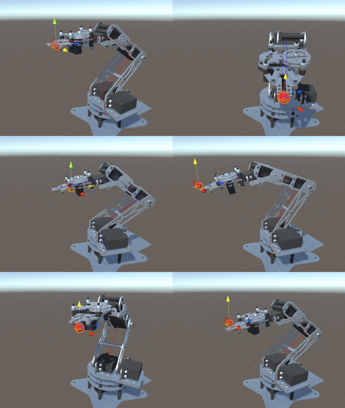
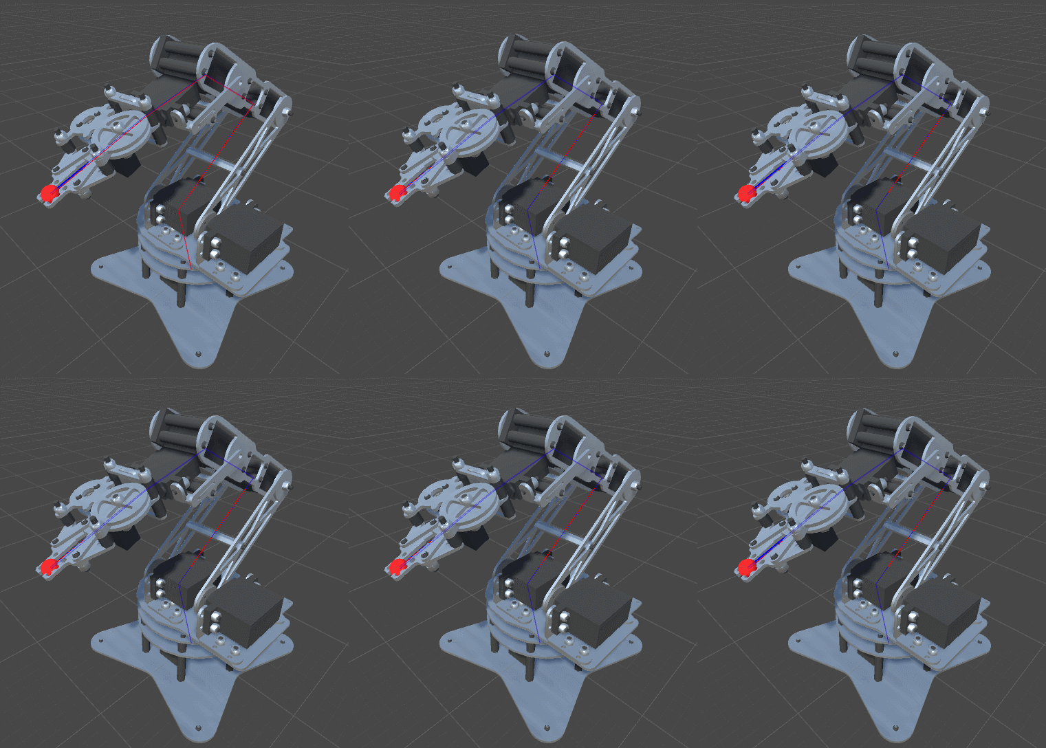
After a long journey about the Mathematics of Forward Kinematics and the geometrical details of gradient descent, we are ready to finally show a working implementation for the problem of inverse kinematics. This tutorial will show how it can be applied to a robotic arm, like the one in the image below.

The other post in this series can be found here:
- Part 1. An Introduction to Procedural Animations
- Part 2. The Mathematics of Forward Kinematics
- Part 3. Implementing Forward Kinematics
- Part 4. An Introduction to Gradient Descent
- Part 5. Inverse Kinematics for Robotic Arms
- Part 6. Inverse Kinematics for Tentacles
- Part 7. Inverse Kinematics for Spider Legs 🚧 (work in progress!)
At the end of this post you can find a link to download all the assets and scenes necessary to replicate this tutorial.
Introduction
The previous tutorial, An Introduction to Gradient Descent, laid the mathematical foundations for a technique called gradient descent. What we have is a function, ![]() , which takes a parameter
, which takes a parameter ![]() for each joint of our robotic arm. That parameter is the current angle of the joint. Given a particular configuration of joints,
for each joint of our robotic arm. That parameter is the current angle of the joint. Given a particular configuration of joints, ![]() , the function
, the function ![]() return a single value indicates how far the effector of the robotic arm is from the target point
return a single value indicates how far the effector of the robotic arm is from the target point ![]() . Our objective is to find the values for
. Our objective is to find the values for ![]() that minimise
that minimise ![]() .
.
To do so, we first calculate the gradient of a function for the current ![]() . The gradient is a vector that indicates the direction of the steepest ascent. To put it simple, it’s an arrow that tells us the direction in which the function grows. Each element of our gradient is an estimation of the partial derivative of
. The gradient is a vector that indicates the direction of the steepest ascent. To put it simple, it’s an arrow that tells us the direction in which the function grows. Each element of our gradient is an estimation of the partial derivative of ![]() .
.
For example, if our robotic arm has three joints, we will have a function ![]() which takes three parameters:
which takes three parameters: ![]() ,
, ![]() and
and ![]() . Then, our gradient
. Then, our gradient ![]() is given by:
is given by:
![]()
where:
![]()
![]()
![]()
and ![]() ,
, ![]() and
and ![]() are sufficiently small values.
are sufficiently small values.
Once we have our estimated gradient ![]() , if we want to minimise
, if we want to minimise ![]() we have to move in the opposite direction. This means updating
we have to move in the opposite direction. This means updating ![]() ,
, ![]() and
and ![]() in this way:
in this way:
![]()
![]()
![]()
where ![]() is the learning rate, a positive parameter that controls how fast we move away from the ascending gradient.
is the learning rate, a positive parameter that controls how fast we move away from the ascending gradient.
Implementation
We have now all the knowledge necessary to implement a simple gradient descent in C#. Let’s start with a function that estimates the partial gradient ![]() of the
of the ith joints. As discussed, what we have to do is to sample function ![]() (which is our error function
(which is our error function DistanceFromTarget defined in An Introduction to Gradient Descent) at two different points:
public float PartialGradient (Vector3 target, float[] angles, int i)
{
    // Saves the angle,
    // it will be restored later
    float angle = angles[i];

    // Gradient : [F(x+SamplingDistance) - F(x)] / h
    float f_x = DistanceFromTarget(target, angles);

    angles[i] += SamplingDistance;
    float f_x_plus_d = DistanceFromTarget(target, angles);

    float gradient = (f_x_plus_d - f_x) / SamplingDistance;

    // Restores
    angles[i] = angle;

    return gradient;
}
When invoked, this function returns a single number that indicates how the distance from our target changes as a function of the joint rotation.
What we have to do is to loop over all the joints, calculating its contribution to the gradient.
public void InverseKinematics (Vector3 target, float [] angles)
{
    for (int i = 0; i < Joints.Length; i ++)
    {
        // Gradient descent
        // Update : Solution -= LearningRate * Gradient
        float gradient = PartialGradient(target, angles, i);
        angles[i] -= LearningRate * gradient;
    }
}
Invoking InverseKinematics repeatedly move the robotic arm closer to the target point.
Early Termination
One of the main problems of inverse kinematics made with such a naive implementation of gradient descent is that it is unlikely to converge. Depending on the values you have chosen for LearningRate and SamplingDistance, it is likely your robotic arm will “wiggle” around the actual solution.

This happens because we update our angles too much, causing the robotic arm to overshoot the actual point. A proper solution to this problem would be to use an adaptive learning rate, which changes depending on how close we are to the solution. A cheaper alternative is to stop the optimisation algorithm if we are closer to a certain threshold:
public void InverseKinematics (Vector3 target, float [] angles)
{
    if (DistanceFromTarget(target, angles) < DistanceThreshold)
        return;

    for (int i = Joints.Length -1; i >= 0; i --)
    {
        // Gradient descent
        // Update : Solution -= LearningRate * Gradient
        float gradient = PartialGradient(target, angles, i);
        angles[i] -= LearningRate * gradient;

        // Early termination
        if (DistanceFromTarget(target, angles) < DistanceThreshold)
            return;
    }
}
If we repeat this check after each joint rotation, we ensure that we perform the minimum amount of movements required.
To further improve the performance of our arm, we can apply gradient descent in reverse order. Starting from the end of the arm, instead of its base, allows us to make the smaller movements. Overall, these little tricks allow to converge to a more natural solution.
Constraints
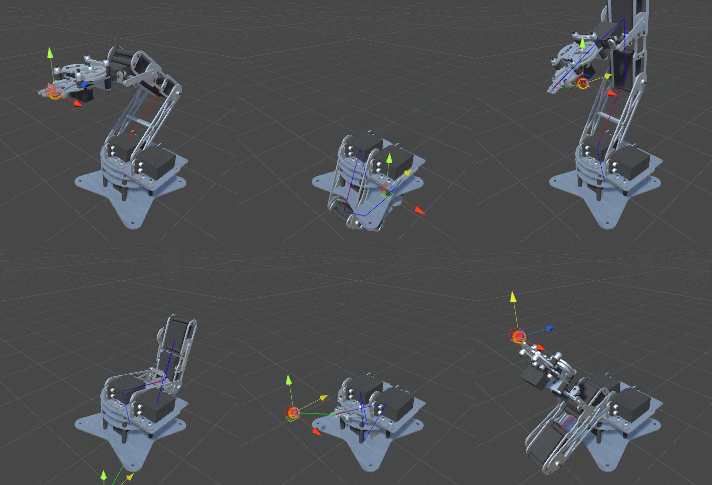
One of the features of real joints is that they tend to have a range of angles they can cover. Not all joints can fully rotate 360 degrees around their axes. Currently, we have put no restrictions on our optimisation algorithm. This means that we are likely to obtain behaviours like this one:

The solution is rather straightforward. We can add minimum and maximum angles in the RobotJoint class:
using UnityEngine;

public class RobotJoint : MonoBehaviour
{
    public Vector3 Axis;
    public Vector3 StartOffset;

    public float MinAngle;
    public float MaxAngle;

    void Awake ()
    {
        StartOffset = transform.localPosition;
    }
}
then, making sure that we clamp the angles in the proper range:
public void InverseKinematics (Vector3 target, float [] angles)
{
    if (DistanceFromTarget(target, angles) < DistanceThreshold)
        return;

    for (int i = Joints.Length -1; i >= 0; i --)
    {
        // Gradient descent
        // Update : Solution -= LearningRate * Gradient
        float gradient = PartialGradient(target, angles, i);
        angles[i] -= LearningRate * gradient;

        // Clamp
        angles[i] = Mathf.Clamp(angles[i], Joints[i].MinAngle, Joints[i].MaxAngle);

        // Early termination
        if (DistanceFromTarget(target, angles) < DistanceThreshold)
            return;
    }
}
Issues
Even with angle constraints and early termination, the algorithm that we have used is very simple. Too simple. There are many issue that you might encounter with this solution, most of them related with gradient descent. As described in An Introduction to Gradient Descent, the algorithm can get stuck in local minima. They represent suboptimal solutions: ways to approach the target that are unnatural or undesirable.
Look at the following animation:

The robotic arm has gone too far, and now that has returned back to its original position, is twisted. A better approach to avoid this is to add a comfort function. If we have reached destination, we should try to re-orient the robotic arm to a more comfortable, natural position. It should be noted that this might not always be possible. Re-orient a robotic arm might force the algorithm to increase the distance from the target, which might be against the specification.
Other resources
- Part 1. An Introduction to Procedural Animations
- Part 2. The Mathematics of Forward Kinematics
- Part 3. Implementing Forward Kinematics
- Part 4. An Introduction to Gradient Descent
- Part 5. Inverse Kinematics for Robotic Arms
- Part 6. Inverse Kinematics for Tentacles
- Part 7. Inverse Kinematics for Spider Legs 🚧 (work in progress!)
Become a Patron!
Patreon You can download the Unity project for this tutorial on Patreon.
Credits for the 3D model of the robotic arm goes to Petr P.
💖 Support this blog
This website exists thanks to the contribution of patrons on Patreon. If you think these posts have either helped or inspired you, please consider supporting this blog.
📧 Stay updated
You will be notified when a new tutorial is released!
📝 Licensing
You are free to use, adapt and build upon this tutorial for your own projects (even commercially) as long as you credit me.
You are not allowed to redistribute the content of this tutorial on other platforms, especially the parts that are only available on Patreon.
If the knowledge you have gained had a significant impact on your project, a mention in the credit would be very appreciated. ❤️🧔🏻


How to speed up robot-arm movement to maximum speed?
Hi ilyxa!
There is no concept of “maximum speed” in IK.
The “speed” is mostly determined by how many iterations it takes to find a solution to the IK problem.
If you need an arbitrary speed, then you need to change the way this works.
A good solution is to calculate the “final” point in a single Update call. Then, when you have it, you can lerp as fast as you want to the target.
Hello, I have a similar project, but not in Unity. and for Arduino. The question is, will I be able to apply the math from this article for the Arduino IDE? Another question, I need to draw a robot arm
on the Board the lemniscate of Bernoulli, how can I do this ? I will be very grateful for your help
Hi Alex!
This solution will work regardless of the language you are using. So yes, it will work on an Arduino as well.
The only problem, however, is that Arduino doesn’t use C#, so you’ll have to adjust the code accordingly.
The hardest bit might be the Maths. Unity comes with a lot of libraries to rotate points in 3D space. Arduino doesn’t have that, so you’ll have to write those equations yourself. I have a tutorial on that as well, hopefully it can help ( https://www.alanzucconi.com/2016/02/03/2d-rotations/ ).
I’m not sure what you mean exactly with your second question.
Thanks for this! If I’m not mistaken, there’s a tiny (literally) typo in the first formula. The last item says f a0 instead of f a2
Thank you!
I’ve corrected it!
Loving the tutorials, been a huge help in some projects of mine. It seems that that part 7 (spider legs) is missing and brings me to an error page. Has it not been finished yet?
Awesome job on the tuts, thanks!
Hey!
I have most of the stuff ready, so hopefully it will be released soon!
ISH! :p
Hi Alan,
Can you possibly help me on how can I make it so that the end-effector can move to a desired position AND orientation? (For robot arm, not tentacle)
Thanks for your help!
This may sound like a very dumb question, but I’m not really sure what to put in the “Angels” bit when i call Inverse Kinematics in Update(); what do i need to put there exactly
Can somebody please help! 🙁
I’m wondering that myself. Although he says: “The name is self-explanatory: angles[i] contains the local rotation for the i-th joint. “, this tells us nothing about which angle of the joint we’re talking about, and on which axis.
Hey!
Angles is an array that, as Micheal highlighted, contains the local rotation for each joint. The inverse kinematics algorithm requires to “explore” how a certain rotation would affect the position of the end effector. You can’t really move the actual robotic arm to test this. So the angles of the joints are copies into this array, and the algorithm changes it until it finds a solution.
In this specific solution, each joint can only rotate on a single axis.
So there is *no* ambiguity. If this is for a 2D game, it will most likely be the Z axis.
The full project is also available on Patreon if you need!
Oh, okay, so it’s a single axis, and the axis depends on where you want to go. Oddly enough though when I aim the tip of my arm to (0,2,0) and use the x axis of the two joints, it doesn’t go anywhere near the target (Arm starts on the floor), Somehow it reaches down. Maybe calling InverseKinematics from the Update() loop with the target vector isn’t right?
I’m trying to figure this out at least a little on my own before I download the project and cheat by just blindly using that.
Your code uses float variables for angles, but the math calculations work with quaternions. How exactly do we get the floats back into the actual quaternion representation when all the calculations are done? For example, we have this:
angles[i] -= LearningRate * gradient;
but then, how would we re-apply it to Joints[i].transform.rotation? We can’t just plug the float value of angles[i] into the quaternion.
Hi.
In that particular implementation, each joint only moves along one axis (X, Y or Z).
You can simply change the localEulerAngle to update the rotation of a joint.
For instance, if you are changing only rotation on the Y axis, you can do:
armTransform.localEulerAngle = new Vector3(0, newY, 0);
Thank you, great tutorial series. Just a question, would it be easier to implement this solution using FABRIK?
I’m talking about this implementation: http://www.andreasaristidou.com/FABRIK.html
Hi Theon!
I am not familiar with FABRIK, so, unfortunately, I can’t really advise you on that.
I know how to use CCD very well, and I am planning on having a tutorial on that relatively soon.
Okay, sorry about the pushiness here, but I see that it’s impossible to download the project without paying $25 on Patreon. In order to consider that I would need to see the final tutorial part with the spider legs completed, and maybe a part thrown in about robot legs, if it isn’t obvious enough from the spider legs part when that’s complete. In order for this to be really worth my time/money, I need to be able to use it to procedurally move procedurally generated robots around a room. (I am making a Berzerk clone in 3D).
I guess it is possible to apply this in C++? I am looking at robotic arms for Orbiter. I can do the rotation but IK is where I have an issue. Thanks
Yes, the technique can be implemented in any language.
Thanks.
Well like I said trying to do a Robotic arm like the JEMRMS.
I can get the distance of the joint:
const double RMS_SP_EP_DIST = length(RMS_EP_JOINT-RMS_SP_JOINT);
// distance (metres) from SP joint to EP joint
const double RMS_EP_WP_DIST = length(RMS_WP_JOINT-RMS_EP_JOINT);
// distance (metres) from EP joint to WP joint
const double RMS_WP_WY_DIST = length(RMS_WY_JOINT-RMS_WP_JOINT);
// distance (metres) from WP joint to WY joint
const double RMS_WY_EE_DIST = length(RMS_WY_JOINT-RMS_EE_POS);
// distance (metres) from WY joint to EE
But calculating the vectors to move the joints is what I haven’t figured out yet?
Hi.
You could help me in how I could do a “Tracking” system, using an IMU sensor.
What I want to achieve is this
https://www.youtube.com/watch?v=I7j6cE30aLQ&t=20s
In which part of the kinematics I could enter the data that the IMU gives me.
Thanks for the help.
What’s the cost function (distanceToTarget) when the robot has a rotation, such as in 6DOF? I find sum(abs(target[x][y]-start[x][y])) naturally gives too much weight to the translation component – the arm will slide to position and fail to match orientation. Please educate me! 🙂
Hi Dan!
That really depends on how you want to achieve this effect!
Personally, I would have the total cost as the sum of two different cost. One could be the distance to the target, and the other could be the “misalignment” of the robotic arm from the object rotation. This could literally be the dot product of the forward vectors of the target and the effector. Then, you can simply do a weighted average of both costs, and decide which one is more important until you get a nice result.
Can’t wait for the Spider tutorial!
In the meanwhile, any ideas on how to improve the Forward Kinematics to take starting localRotations into account? I’ve been trying to tackle this for the past week and limbs are flying everywhere haha
Just a note to anyone doing this. If you use transform.localRotation (a quaternion) instead of using an angles[], and if you just remember to reset the localRotation of each joint after calculating the partial gradient (i.e. set localRot to be transform.localRotation * quaternion.axisAngle(sampleDistance, joints[i].axis and then test the new Distance) One you have less fields to keep track of, and Two you can rotate your arm joints anyway you want in the inspector without having to manually set the angles[] before hitting play.
Thank you for this! unfortunately the solution to limit the angle is far from ideal, sometimes my robot could totally reach the target, but it tries another path instead, one that exceeds its limits, which makes the angle freeze in the limit and never reach the target that is totally within reach if it tries another route
Hi Alan, would you mind to share the full coding scripts to me as I am working on a similar project recently. And I am facing some problems on coding it. It will be grateful if you could share this to me. Thank you!
Do you think the performance of this algorithm would be improved if you used regularization parameters, or in other words turned this into a constrained optimization problem using lagrangian multipliers (as is common in multiple linear regression ML problems) as opposed to simply clamping the angle values?
this is great article explained very well
Thank you so much!
spider spider spider spider