
This tutorial will teach you how to recreate a very popular effect in games: topographical maps.
This is a two-part series, which will cover all the necessary aspects—from the Maths to the shader code—to make this possible:
In this second part, we will focus on the edge detection algorithm that will be used to draw the contours of the terrain.


A link to download the full Unity package is also available at the end of the tutorial.
Introduction
Let’s start with a simple fact: drawing lines in a shader is hard. And the reason is actually simple: the concept of line follows the semantic of object contour. Intuitively we know where a separation line between two objects should be, because we know where an object ends and another one starts. But at a shader level, this semantic information is completely lost. Shaders, in fact, only work at the level of vertices and pixels, ignoring the bigger picture.
This is why both crisp outlines and wirelines are notoriously hard to do in videogames. As a result, there are a variety of different techniques used in videogames to draw lines. Alexander Ameye wrote a very insightful article showing 5 ways to draw an outline in Unity. Although there are many more, each one with its own advantages and drawbacks. Another very interesting read on a similar topic is Ben Golus’ recent article titled The Quest for Very Wide Outlines.
Despite the difficulty, creating a solid aesthetics through the use of outlines is possible. Many games did an incredibly good job, such as Shedworks’ Sable, which is heavily inspired by the work of (Jean Giraud also known as Moebius).
Another title which heavily bases its aesthetics on crisp lines is Lightmatter.

Both games relies on a very simple technique to achieve their looks: postprocessing. This means that the lines are actually drawn in screen space after the geometry has been rendered, and that this is done on the image generated from the camera, not on the actual 3D models. While not cheap, postprocessing allows to easily do something that would otherwise be very tricky: creating crisp lines with constant thickness. Because lines are drawn on the final image, their thickness will be the same regardless of an object position in 3D space. A typical drawbacks of drawing outlines directly on the object is that their sizes change according to the perspective. By relying on postprocessing, we do not need to worry about compensating for line thickness based on the distance from the camera.
But how are lines drawn around objects, when rendered images have no notion of where objects are? Here’s the trick: we can render each object with a different colour, and then using postprocessing to perform some kind of edge detection.
Back in 2018, George Batchelor posted a very interesting breakdown of how he achieved crisp outlines in Bird Alone, in a process that was directly inspired by Sable:


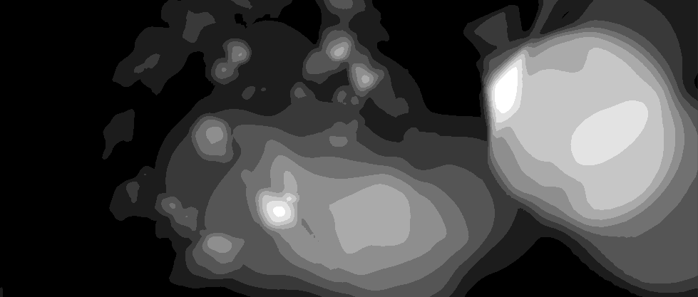
The way in which this worked is deceptively simple: each part of the scene is initially drawn in a different colour. Postprocessing is then used to identify the edges (i.e.: the pixels which neighbours are not of the same colours). And finally, a textured render can be composited together with the outlines:

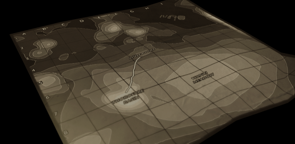
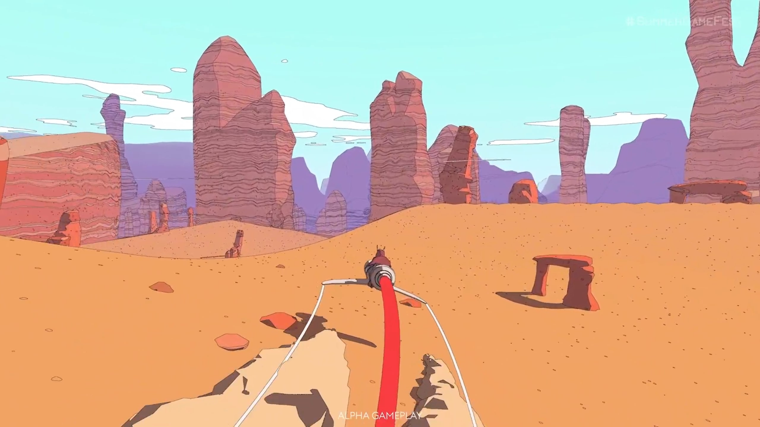
This tutorial is going to show you how to do exactly the same. But the starting point will be the shaded terrain that was done back in Part 1:
If you are interested in similar effects, I would highly recommend to check out Lucas Pope’s exceptional devlogs explaining how he achieved many of the incredible effects for his game, Return of the Obra Dinn. Its dithering effect is also explored in details in Shader Showcase Saturday #11.
If you need something more professional for your project, I would suggest SC Post Effect Pack from the Unity Asset Store. It includes a variety of edge detection solutions, working both on input colours, depth or normals. You can check it out here:
Effect Anatomy
Making this effect in Unity requires two parts: an edge detection shader (which is where the computation will actually take place) and a C# script that applies it to the rendered texture generated from the camera.
The Theory of Edge Detection
While the latter is fairly straightforward, the former requires a bit of explanation. How can a shader detect edges? As mentioned before, the concept of edge is semantic. However, what we really want is to focus on detecting sharp changes in colour between nearby pixels. As you can imagine, this can be problematic because two separate objects might have the same colour (such as the leaves of a tree, or the different shades of a smooth object), and deciding “how different” two pixels should be to be considered two separate objects is not a trivial task. Luckily for us, these are problems that only occur when rendering complex geometry. In our case, we are only dealing with a terrain shaded with a ramp texture. Solely relying on colours comes at the risk of having artefacts, but as long as the geometry is relatively tamed, there should not be too many noticeable glitches.
Some other games relies on edge detection on the z-buffer, meaning that they consider two pixels to be separate if they are “further enough” from each each.
Our edge detection effect will decide if a pixel is part of the “edge” based on the neighbouring pixels. Many effects of this kind can be perform using an operation known as a convolution. A convolution associates a number to each pixel, based on weighted average of the ones surrounding in a (typically) 3×3 area. The idea is to multiply the value of each pixel by a certain value, and then summing all up. The multiplying coefficients for 3×3 convolution can be stored in a 3×3 matrix, which indicates how much “weight” each pixel should bear on the final result.
What makes this approach interesting is that it provides a “standardised” system to perform image processing, which can be tweaked solely by changing the input matrix (typically referred to as a convolution matrix or kernel). Different weights combinations, in fact, lead to a huge difference in the the final result. They are typically used for things like blurring, and sharpening. If you want to learn more about how kernels work, and to try them directly, I would suggesting checking the explorable explanation Image Kernels from Explained Visually (below).
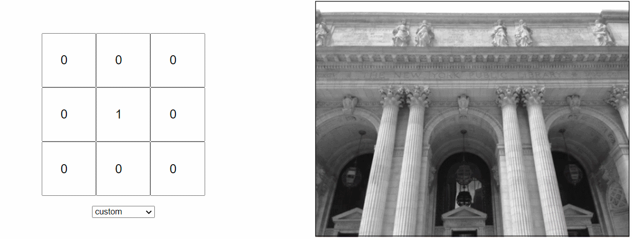
There are several convolution matrices that can be used for edge detection as well. The two most popular ones are the Sobel and the Laplacian edge detector. The latter has the following kernel:

If you have encounter the Laplacian kernel already, you might have also seen it with its signed flipped, or in a slightly different version which does not include the edges:

In this tutorial, we will use this second version of the Laplacian kernel. The reason is that each component requires to access a different pixel. Texture sampling is a notoriously expensive operation to perform in a shader, and so the fewer samples are done, the more computationally efficient this effect will be. Four elements of the kernel are zero, which means that their respective four pixels will bear no weight on the edge detection calculation and do not need to be sampled.
It is interesting to understand why the Laplacian kernel detect edges. Let’s start by understand when it does not, which is when its output is  : in the case of a black and white image, this happens when all pixels have the same value. In that case, in fact, the contribution of the four neighbouring pixels cancel out with the centre pixel. It should be now much clear to see why this filter detect “imbalances” in pixel colours.
The Laplacian kernel is very sensitive to noise, which means that it can introduce several artefacts. For general application, images are often blurred before applying this filter. This smooths the image out, removing a lot of the finer details which could be erroneously interpreted by the filter as edges.
You can read more about the mathematics behind this technique in The Sobel and Laplacian Edge Detectors.
📚 Sobel Edge Detection
There are several other ways in which edge detection is performed using kernels. Another very popular option is known as Sobel edge detection. Instead of using a single kernel, it uses two: one for the horizontal edges ( ) and one for the vertical edges (
 ):
):


The two kernels above, in fact, strongly react to features that present horizontal or vertical changes in colour.
These two are usually combined using Pythagoras’s theorem to compute the final effect:

Sobel and Laplace are some of the most popular techniques to detect edges, but are not not the only ones. Comparing Edge Detection Methods is an interesting read if you want to find out about other techniques, such as the Prewitt and Canny edge detection.
⭐ Recommended Unity Assets
Unity is free, but you can upgrade to Unity Pro or Unity Plus subscription plans to get more functionalities and training resources for your games.
The Shader
The starting point for a postprocessing effect in Unity using the built-in render pipeline is a vertex and fragment shader. In case you are not too familiar with the process, it has been covered extensively in Screen Shaders and Image Effects in Unity, which shows how to create a few simple postprocessing effects. Recent versions of Unity also include a template for post-processing shaders that you can find in the context menu under “Create > Shader > Image Effect Shader”.
The idea is to create a shader which will work on the image rendered by the main camera. Once the shader has done its pass, this new image is then displayed to the player instead of the original one.
Shaders typically work locally, as each pixel is drawn independently from the others. In this case, however, the resulting colour depends on the nearby pixels. This shader needs to address individual pixels, and to do so it needs to know the “size” of a pixel. In a screen shader, the image rendered by the camera is addressed in UV space: this is a coordinate system which starts in one corner, with both axes ranging from to  . The size of a pixel in UV space is hence given by the screen resolution:
  .
.
Unity has an easy way to access these two values, using _MainTex_TexelSize:
sampler2D _MainTex;
float4 _MainTex_TexelSize; // float4(1 / width, 1 / height, width, height)
In fact, _MainTex_TexelSize.xy represents the size of a pixel in UV space.
Step 1: Texture Sampling
Now that we know the size of a pixel in UV space, we can start writing code to sample the nearby ones. The fragment function, frag, is the one that needs to sample the texture in several different points, starting from i.uv which are the coordinates of the current pixel being drawn by the shader:
float3 C = tex2D(_MainTex, i.uv).rgb;
float3 N = tex2D(_MainTex, i.uv + fixed2(0, _MainTex_TexelSize.y) ).rgb;
float3 S = tex2D(_MainTex, i.uv - fixed2(0, _MainTex_TexelSize.y) ).rgb;
float3 W = tex2D(_MainTex, i.uv + fixed2(_MainTex_TexelSize.x, 0) ).rgb;
float3 E = tex2D(_MainTex, i.uv - fixed2(_MainTex_TexelSize.x, 0) ).rgb;
Step 2: Pixel Luminance
What is available right now in the C, N, S, W, and E variables is the colours of the pixels, stored as their RGB components. The convolution, however, works on individual elements, not colours. For this reason, edge detection filters are typically applied to greyscale images.
An easy way to do so is to convert those colours into their perceived luminance. This is a metric that loosely indicates how bright a colour is. While far from being perfect (see The Secrets of Colour Interpolation for a deeper explanation), it is more than enough for our application.
The perceived luminance can be calculated as a linear combination of the R, G and B components of a colour, using the following expression:
#define LUM(c) ((c).r*.3 + (c).g*.59 + (c).b*.11)
This is an equation that takes into account how the human eye perceives colours, and its sensitivity to different wavelengths (source: W3C).
📚 Shader code and macros
If you are familiar with C and C++, chances are that you know what macros are. But if you are not, the following line of code might have been rather confusing:
#define LUM(c) ((c).r*.3 + (c).g*.59 + (c).b*.11)
Macros are a way to define “lightweight functions”. In fact, the macro defined above is functionally equivalent to the following function:
float LUM (float3 c)
{
    return c.r*.3 + c.g*.59 + c.b*.11;
}
The difference is in how they work. Macros, in fact, are not “real” functions: they are text substitutions. So every time you write LUM(c), the compiler will replace it with c.r*.3 + c.g*.59 + c.b*.11. This is regardless of the context, and ignoring whether or not this actually makes sense.
Because macros are effectively text substitutions, they are “executed” at compilation time and do not require the amount of resources that functions need (although usually negligible) to be invoked.
Step 3: Laplacian
Once we have a way to convert a colour into its perceived luminance, we have everything we need to calculate the Laplacian:
// Luminosity
float C_lum = LUM(C);
float N_lum = LUM(N);
float S_lum = LUM(S);
float W_lum = LUM(W);
float E_lum = LUM(E);

// Laplacian
float L_lum = saturate(N_lum + S_lum + W_lum + E_lum - 4 * C_lum);
This represents the result value of the edge detection algorithm.
Final Colour
The Laplacian can have pretty much any value. If we use its results as the final output of the shader, we will have a rather blurry set of lines. To clean this up, we cam simply use a threshold to decide which values to set to zero, and which one to keep:
L_lum = step(_MapThreshold, L_lum);
return float4(L_lum, L_lum, L_lum, 1);
The result is indeed the set of lines that we were looking for.
The Postprocessing
The last step (this time for real!) is to make sure that the shader we made in the previous section can be used to process the frames generated by the main camera. This is a pretty standard technique, which was covered in one of my very first tutorials, Screen shaders and image effects in Unity3D, which is part of the Gentle Introduction to Shaders series.
[ExecuteInEditMode]
public class LaplacianEffect : MonoBehaviour
{
    public Material Material;

    // Postprocess the image
    void OnRenderImage(RenderTexture source, RenderTexture destination)
    {
        Graphics.Blit(source, destination, Material);
    }
}
It is worth to mention that this specific piece of code only works with the built-in render pipeline. Both URP and HDRP work differently, and so creating a postprocessing shader is not-so straightforward. Just to give you an idea, HDRP alone has three different stages in its render pipeline which can be used to do various different effects: Before Transparent, Before Post Process and After Post Process. In this blog we will not cover how to implement this effect for the URP or HDRP pipelines, but the theory behind it remains the same.
❓ What does ExecuteInEditMode mean?
You might have noticed that the postprocessing script started included the [ExecuteInEditMode] line. This is what C# calls an attribute, and is a notation used to add special properties to classes, members and methods. In this case, [ExecuteInEditMore] is telling Unity that this script should run even when the game is not. This means that every time the Game window is rendered, the OnRenderImage function of the script will be invoked and with it its postprocessing effect.
Without that attribute, the game will only render outlines when running, or in the final build.
Attach to Camera
All that is left now to do is to create a material with the edge detection shader, and to attach the postprocessing script to the camera.
The effect is now complete! If you need something more sophisticated, you can extend the postprocessing script to compose the original camera render and its outline in a different way. For instance, to impress the contour lines onto a shaded version of the terrain. This would actually work really well for a topographical map. While not covered in this series, the Unity package that you can find at the end of the article will indeed include that.
Conclusion
This tutorial showed how to create topographical maps in Unity, using shaders and postprocessing. You can find all the parts in this series here:
A follow-up series will cover how to render the map to make it look like paper.
Download Unity Package
Become a Patron!The Unity package contains everything needed to replicate the visual seen in this tutorial, including the shader code, the C# scripts, and a test scene with the terrain.
Leave a Reply