

You can read the rest of this online course here:
A follow-up that focuses on 3D is also available:
- Part 3. Inverse Kinematics in 3D
Introduction
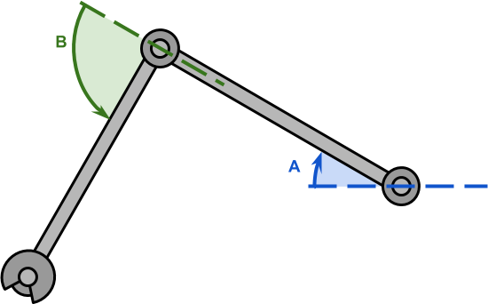
In the previous part of this series, we have discussed the problem of inverse kinematics for a robotic arm with two degrees of freedom; like the one in the diagram below.
In such a scenario, the length of the robotic arms,  and
and  , is typically known. If the point we have to reach is
  , then the configuration becomes a triangle in which all sides are known.
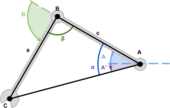
We have then derived the equations for the angles  and
and  , which controls the rotation of the robotic arms’ joints:
(1) 
(2) 
At a first glance, they might look rather intimidating; their geometrical interpretation, on the other hand, should be farily intuitive looking at the diagram above.
Creating the Robotic Arm
The first step to implement this solution is to create a robotic arm. The concept of “joints” is not something that Unity comes with. However, the parenting system offered by the engine can be exploited to create a hierarchy of components that will behave exactly like a robotic arm.
The idea is to use a GameObject for each joint, so that rotating its transform will cause the arm attached to it to rotate as well. Parenting the second joint to the first joint will cause them to rotate like seen in the first diagram.
The resulting hierarchy becomes:
- Root
- Joint A
- Bone A
- Joint B
- Bone B
- Hand
- Joint A
We can then add a script to the root object called SimpleIK, which will take care of rotating the joints to reach the desired target.
using System.Collections;
using UnityEngine;

namespace AlanZucconi.IK
{
    public class SimpleIK : MonoBehaviour
    {
        [Header("Joints")]
        public Transform Joint0;
        public Transform Joint1;
        public Transform Hand;

        [Header("Target")]
        public Transform Target;

        ...
    }
}
The equations derived in the previous part of this tutorial require knowing the length of the first two bones (called and , respectively). Since the length of the bones is not supposed to change, it can be calculated in the Start function. This, however, requires the arm to be in a good configuration when the game starts.
private length0;
private length1;

void Start ()
{
    length0 = Vector2.Distance(Joint0.position, Joint1.position);
    length1 = Vector2.Distance(Joint1.position, Hand.position  );
}
Rotating the Joints
Before showing the final version of the code, let’s start with a simplified one. If we translate equations (1) and (2) directly to code, we end up with something like this:
void Update ()
{
    // Distance from Joint0 to Target
    float length2 = Vector2.Distance(Joint0.position, Target.position);

    // Inner angle alpha
    float cosAngle0 = ((length2 * length2) + (length0 * length0) - (length1 * length1)) / (2 * length2 * length0);
    float angle0 = Mathf.Acos(cosAngle0) * Mathf.Rad2Deg;

    // Inner angle beta
    float cosAngle1 = ((length1 * length1) + (length0 * length0) - (length2 * length2)) / (2 * length1 * length0);
    float angle1 = Mathf.Acos(cosAngle1) * Mathf.Rad2Deg;

    // Angle from Joint0 and Target
    Vector2 diff = Target.position - Joint0.position;
    float atan = Mathf.Atan2(diff.y, diff.x) * Mathf.Rad2Deg;

    // So they work in Unity reference frame
    float jointAngle0 = atan - angle0;	// Angle A
    float jointAngle1 = 180f - angle1;	// Angle B

    ...
}
The mathematical functions  and
and  are called
 Mathf.Acos and Mathf.Atan2 in Unity. Also, the final angles are converted to degrees using Mathf.Rad2Deg, since the Transform component accepts degrees, instead of radians.
Aiming to Unreachable Targets
While the code above seems to work, there is a condition in which it fails. What happens if the target is unreachable? The current implementation does not take that into account, resulting in undesirable behaviours.
A common solution is to fully stretch the arm in the direction of the target. Such a behaviour is consistent with the reaching movement that we are trying to simulate.
The code below detects if the target is out of reach by checking if the distance from the root is greater than that the total length of the arm.
void Update ()
{
    float jointAngle0;
    float jointAngle1;

    float length2 = Vector2.Distance(Joint0.position, Target.position);

    // Angle from Joint0 and Target
    Vector2 diff = Target.position - Joint0.position;
    float atan = Mathf.Atan2(diff.y, diff.x) * Mathf.Rad2Deg;

    // Is the target reachable?
    // If not, we stretch as far as possible
    if (length0 + length1 < length2)
    {
        jointAngle0 = atan;
        jointAngle1 = 0f;
    }
    else
    {
        float cosAngle0 = ((length2 * length2) + (length0 * length0) - (length1 * length1)) / (2 * length2 * length0);
        float angle0 = Mathf.Acos(cosAngle0) * Mathf.Rad2Deg;

        float cosAngle1 = ((length1 * length1) + (length0 * length0) - (length2 * length2)) / (2 * length1 * length0);
        float angle1 = Mathf.Acos(cosAngle1) * Mathf.Rad2Deg;

        // So they work in Unity reference frame
        jointAngle0 = atan - angle0;
        jointAngle1 = 180f - angle1;
    }

    ...
}
Rotating the Joints
What’s left now is to rotate the joints. This can be done accessing the localEulerAngles property of the joints’ Transform component. Unfortunately, it is not possible to change the z angle directly, so the vector needs to be copied, edited and replaced.
Vector3 Euler0 = Joint0.transform.localEulerAngles;
Euler0.z = jointAngle0;
Joint0.transform.localEulerAngles = Euler0;

Vector3 Euler1 = Joint1.transform.localEulerAngles;
Euler1.z = jointAngle1;
Joint1.transform.localEulerAngles = Euler1;
Conclusion
This post concludes the course on Inverse Kinematics for 2D robotics arms.
You can read the rest of this online course here:
A follow-up that focuses on 3D is also available:
- Part 3. Inverse Kinematics in 3D
The line art animals that have been featured in this tutorials have been inspired by the work of WithOneLine.
Download
Become a Patron!
You can download all the assets used in this tutorial to have a fully functional robotic arm for Unity.
| Feature | Standard | Premium |
| Inverse Kinematics | ✅ | ✅ |
| Multiple Solutions | ❌ | ✅ |
| Smooth Reaching | ❌ | ✅ |
| Test Scene | ❌ | ✅ |
| Test Animations | ❌ | ✅ |
| Download | Standard | Premium |

💖 Support this blog
This website exists thanks to the contribution of patrons on Patreon. If you think these posts have either helped or inspired you, please consider supporting this blog.
📧 Stay updated
You will be notified when a new tutorial is released!
📝 Licensing
You are free to use, adapt and build upon this tutorial for your own projects (even commercially) as long as you credit me.
You are not allowed to redistribute the content of this tutorial on other platforms, especially the parts that are only available on Patreon.
If the knowledge you have gained had a significant impact on your project, a mention in the credit would be very appreciated. ❤️🧔🏻
Hi,
Nice article. Have you ever looked into Geometric Algebra ? It’s coordinate free approach allows for a very elegant coordinate-free formulation of these types of problems. (and generalizes without changes to higher dimensions)
My geometric algebra library comes with a 2D inverse kinematics example. The IK solver is six lines and does not reference any coordinates. If you like take a look on github.com/ganja.js, then examples – 2D PGA IK. (wordpress wont let me link it 😉 )
Cheers,
Steven
Thank you, that’s interesting!
I’ve been wanting to add more interactive examples to my website, but is hard to find good (and simple) frameworks to use!
*cough* that’s github.com/enkimute/ganja.js .. mea culpa.
Would be great if you could provide a bare-minimum project sample and not assume that everyone has the funds to subscribe to Patreon. Nonetheless, your content is very helpful for someone to get the basic idea.
how you drawing this line in GIF in Unity ?
It’s a trail renderer attached to the end effector of the robotic arm!
I think I get the Mathematic part, but I can’t get the code to work.
I don’t get any errors but the script won’t work in Unity. Also the structure of the downloaded script is totally different then in the tutorial. This makes it very hard for me to bugfix the code.
Previous tutorials struggled with the same problem. Maybe it’s my lack of C#, but even with the assets I can’t figure these tutorials out.
Awesome, thank you for the sound introduction to this!
One small addition: In case your “ellbow” is mirrored, aka bending the wrong way (for which Unit’s IK solution has that “flip” toggle), you can flip it by adding this at the end:
jointAngle0 = 2 * atan – jointAngle0;
jointAngle1 = -jointAngle1;
Thanks!
Hi Alan, thank you so much for making this tutorial, your IK implementation is working great for me!
One question though: What would be the best way to implement a local offset to the IK endpoint? More specifically, if I wanted the player’s arm to hold a weapon with a muzzle point that is above the level of the arm, how would I go about offsetting the IK system to compensate for this so that the projectile vector of the weapon passes through the control point, instead of the center of the hand?
In case my explanation isn’t clear, here is a diagram of what I’m after:
https://i.imgur.com/UotR2H0.png
I feel like this should be a simple adjustment, but for whatever reason I can’t quite wrap my head around the necessary translations and rotations needed to achieve this. Any help at all would be greatly appreciated!
Hey, this was amazingly helpful, but in my program the end effector’s position doesn’t seem to coincide with the target’s position even if it’s reachable, could you tell me as to why this is happening? i want the end effector’s position to be the same as target’s position all the time if possible. thank you
Hi Jacob! Unfortunately is very difficult to know why that happens without debugging your project! I think the best way to check where the problem is to plot the result of the gradient descent algorithm, and see if by moving the arm manually according to that you reach the target. This tells you if the problem is the gradient descent not finding the correct value, or the code to set up the arm!