
This post completes the journey started in The Mathematics of Thin-Film Interference, by explaining how to turn the equations previously presented into actual shader code.
You can find the complete series here:
- Part 1. The Nature of Light
- Part 2. Improving the Rainbow (Part 1)
- Part 3. Improving the Rainbow (Part 2)
- Part 4. Understanding Diffraction Grating
- Part 5. The Mathematics of Diffraction Grating
- Part 6. CD-ROM Shader: Diffraction Grating (Part 1)
- Part 7. CD-ROM Shader: Diffraction Grating (Part 2)
- Part 8. Iridescence on Mobile
- Part 9. The Mathematics of Thin-Film Interference
- Part 10. Car Paint Shader: Thin-Film Interference
A link to download the Unity project used in this series is also provided at the end of the page.
Introduction
In the previous post, we derived the equations that govern the process of thin-film interference. In a nutshell, this is an optical phenomenon that occurs when light “bounces” inside a medium which thickness is comparable to the light wavelength.
When this happens, there is a chance that some of the light immediately reflected off the surface will end up interfering with the light refracted inside the medium.
Because the two rays travels different lengths, they might end up off-phase. This means that even if the wavelengths started at the same phase, by the time both rays leave the material surface, their phases might be out of alignment.
This situation causes some wavelengths to interfere constructively, and some to interfere destructively. This means that some colours will be amplified, while other will cancel each other out. As a result, this effect causes unusual reflections, which are strongly dependent on both the view angle and the light angle.
In real life, this effect is predominantly visible in soap bubbles, which displays beautiful iridescent colours.

The effect is also commonly seen in oil spills, and are predominant in certain metals such as bismuth. In the latter, this is due to the fact that the entire surface is covered in a thin film of bismuth(III) oxide. Companies like The Bismuth Smiths have found a way to control the thickness of this oxidised layer, allowing them to master full control over the colour of those crystals.
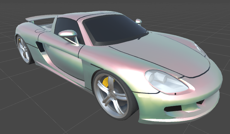
More notoriously, thin-film interference is exploited in many iridescent car paints, such as the ones seen in this video:
Implementation
The quickest way to implement this effect is to retrofit the existing iridescent shader created in part 2 of the CD-ROM Shader: Diffraction Grating series. This is because most of the code is identical, with the small exception of the LightingDiffraction function which will need to implement the new equations.
In the previous tutorial, we have seen the mathematical condition necessary for thin-film to occur for a given wavelength. Its wavelength ( ) must be an integer multiple of
  , where:
 : the refractive index of air,
 : the refractive index of the thin-film,
 : the refractive index of the material,
 : the thickness of the thin-film,
 the angle of reflection,
 the angle of refraction inside the medium.
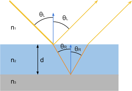
as seen in this diagram:
Our shader code, has only access to the light direction  , the view direction
  and the world normal
  . The value of is easy to find, as the dot product between and is
  .
.
Finding the value of is trickier, but can be done through Snell’s law:
![\[n_1 \sin{\theta_L} = n_2 \sin{\theta_R}\]](https://www.alanzucconi.com/wp-content/ql-cache/quicklatex.com-f1fa61de5820e1d803f1ee8111cc03eb_l3.png "Rendered by QuickLaTeX.com")
from which we can easily extract :
![\[\sin{\theta_R} = \frac{n_1}{n_2} \sin{\theta_L}\]](https://www.alanzucconi.com/wp-content/ql-cache/quicklatex.com-a0ed842669c99bda807196658bf6df5a_l3.png "Rendered by QuickLaTeX.com")
![\[\theta_R = asin{\left(\frac{n_1}{n_2} \sin{\theta_L}\right)}\]](https://www.alanzucconi.com/wp-content/ql-cache/quicklatex.com-645981b76c2be11ac771bc25cd43cecd_l3.png "Rendered by QuickLaTeX.com")
In shader code, this becomes:
	// --- Diffraction grating effect ---
	float3 L = gi.light.dir;
	float3 V = viewDir;
	float3 N = worldNormal;

	// Reminder:
	//     thetaL = angle from L to N
	//     thetaR = angle from reflected L inside material to N
	// From Snell's Law:
	//     N1 * sin(thetaL) = N2 * sin(thetaR)
	float cos_thetaL = dot(N, L);
	float thetaL = acos(cos_thetaL);

	float sin_thetaR = (_N1 / _N2) * sin(thetaL);
	float thetaR = asin(sin_thetaR);
We can now use thin-film interference condition to find if a given wavelength is reflected back to the viewer:
	float u = _N2 * 2 * d * abs(cos(thetaR));

	fixed3 color = 0;
	for (int n = 1; n <= _Order; n++)
	{
		// Constructive interference
		float wavelength = u / n;
		color += spectral_zucconi6(wavelength);
	}
	color = saturate(color);
Here, we have used the same trick used in the CR-ROM shader. Instead of looping through all possible wavelengths (calculating if each interferes constructively or destructively) we check all integer multiples of (called u in the code).
This, unfortunately, is not enough to get to the real effect. There is only a small problem we need to fix. Under certain circumstances, the phase can shift by 180 degrees. This happens when a ray of light travels from a material to another, and the first refractive index is lower than the second.
Our code needs to check if this shift happens on both reflections:
	// Phase shift?
	// A phase shift of 180 degrees occurs on the reflected ray when
	// travelling from A to B AND NA < NB
	float shift = 0;
	if (
		// Phase shift of first ray
		(_N1 < _N2)
		!=
		// Phase shift of second ray
		(_N2 < _N3)
	)
		shift += 0.5;
Once we have the shift, we can simply add it to n to obtain the correct phase shift that light goes through when bouncing into the thin-film.
You can’t. Not if you want a physically based effect. That being said, you can replace the spectral_zucconi6 function with a texture ramp of your choice. By doing this, you can change the rainbow reflection into one you like better.
However, doing so causes the effect to lose any connection with the physical mechanism that causes thin-film interference. In such a case, you might be better to just fake the effect entirely, for instance using a fake BRDF shader like the one presented in Iridescence on mobile, which bakes the reflection into an easily editable texture.
Conclusion
This tutorial completes the series about iridescent material.
You can find the complete series here:
- Part 1. The Nature of Light
- Part 2. Improving the Rainbow (Part 1)
- Part 3. Improving the Rainbow (Part 2)
- Part 4. Understanding Diffraction Grating
- Part 5. The Mathematics of Diffraction Grating
- Part 6. CD-ROM Shader: Diffraction Grating (Part 1)
- Part 7. CD-ROM Shader: Diffraction Grating (Part 2)
- Part 8. Iridescence on Mobile
- Part 9. The Mathematics of Thin-Film Interference
- Part 10. Car Paint Shader: Thin-Film Interference
You can download the Unity package for the CD-ROM Shader effect on Patreon.
💖 Support this blog
This website exists thanks to the contribution of patrons on Patreon. If you think these posts have either helped or inspired you, please consider supporting this blog.
📧 Stay updated
You will be notified when a new tutorial is released!
📝 Licensing
You are free to use, adapt and build upon this tutorial for your own projects (even commercially) as long as you credit me.
You are not allowed to redistribute the content of this tutorial on other platforms, especially the parts that are only available on Patreon.
If the knowledge you have gained had a significant impact on your project, a mention in the credit would be very appreciated. ❤️🧔🏻
Hi Alan,
When will this post be finished? I am waiting for this. 🙂
Please continue this, I would love to see how the car paint setup works, it’s why I became a supporter.
Hi Thomas!
Thank you for your message!
The GIF you see is the actual result of the shader I created.
It is very similar in its structure to the one used for the CD-ROM shader, but the core equation is different.
I haven’t had the time to finish this series yet, but I’ll get back to it, no worries!
just realized this is not finished yet after upgrading the patreon. seems this is hanging like this for quite some time. would really like to have a closure on this awesome series
I’ve replied on Patreon! 🙂
Hey Alan, I want to continue this tutorial series so I went to subscribe to your Patreon but 8$ doesn’t appear to be a tier anymore. What tier should I sign up at?
Great series! Too bad that this last part is still incomplete – there’s no mention of how the end result might be used for specularity involving the view direction, nor where and how the phase shift calculated gets incorporated into the mix..