

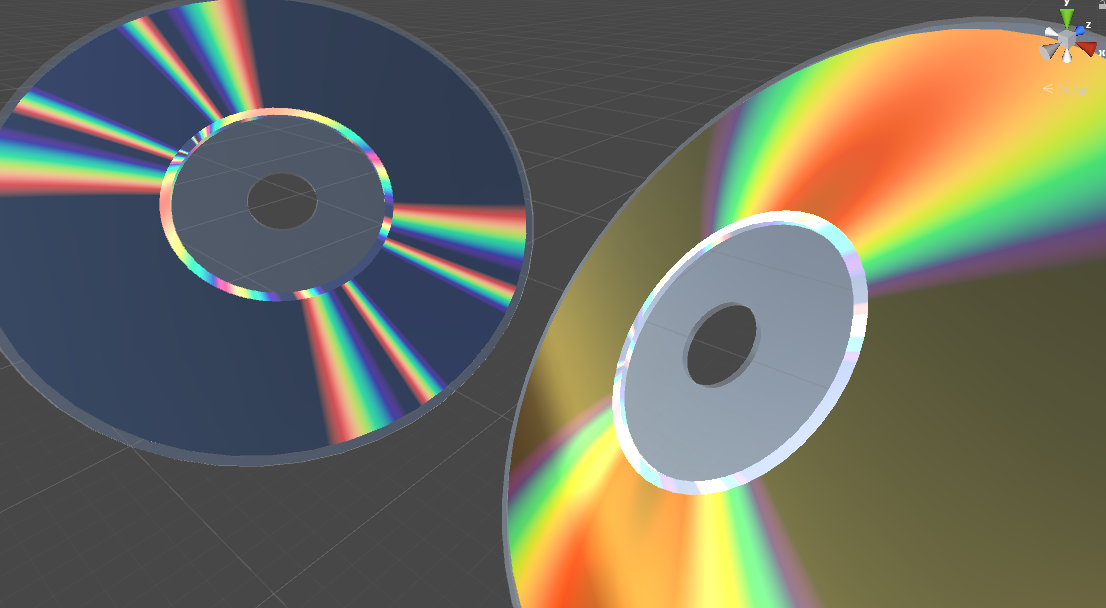
This post introduces the mathematics behind the optical phenomenon known as diffraction grating, which is responsible for iridescent reflections in many materials.
You can find the complete series here:
- Part 1. The Nature of Light
- Part 2. Improving the Rainbow (Part 1)
- Part 3. Improving the Rainbow (Part 2)
- Part 4. Understanding Diffraction Grating
- Part 5. The Mathematics of Diffraction Grating
- Part 6. CD-ROM Shader: Diffraction Grating (Part 1)
- Part 7. CD-ROM Shader: Diffraction Grating (Part 2)
- Part 8. Iridescence on Mobile
- Part 9. The Mathematics of Thin-Film Interference
- Part 10. Car Paint Shader: Thin-Film Interference
A link to download the Unity project used in this series is also provided at the end of the page.
Introduction
The previous post in this series, Understanding Diffraction Grating, explained why iridescence occurs on some materials. Light is a wave, and it bends every time it finds an obstacle in its path. If a material presents a microscopic slit or a bump, this will an incoming planar wave to scatter in all direction. If those slits or bumps are arranged in a regular pattern, a new wavefront is generated for each one of them. All those wavefronts will interfere with each other, causing certain wavelengths (which are perceived by the human eye as colours) to appear prominently.
We now have everything we need to start modelling this phenomenon mathematically. Let’s start by imagining a material which features imperfections that repeat at a known distance  . For the purpose of this derivation, the angle between the incident light rays and the surface normal is
  in. Let’s also imagine that the viewer is oriented in such a way that they receive all the reflected rays with angle . Each imperfection scatters light in all directions, so there will always be rays of light aligned with the viewer, regardless of .

Since the imperfections repeat regularly every nanometres, the scattering pattern itself repeats every nanometres. This means that there will be at least a light ray reaching the viewer for each slit.
Derivation
The two rays of light depicted in the diagram above travel different distances before reaching the viewer. If they start in phase, they might not be when they arrive at their destination. To understand how those two rays interfere with each other (constructively or destructively) we have to calculate how off phase they are when they reach the viewer.
Those two rays are guaranteed to be in phase until the first one hit the surface. The second ray travels an extra a distance  (in green) before hitting the surface as well. Using some simple trigonometry, it can be seen that the length of the green segment is
  .
.
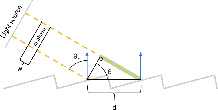
Using a similar construction, we can calculate the extra distance  that the first ray travels towards the viewer before the second hit. In this case, we can see that
  .
.

Those two segments are critical to determining whether the two rays are still in phase or not when they are finally detected. Their difference measures the difference in length of those two rays. If it is zero, we know for sure that the two rays are in phase, since they have effectively travelled the same distance.
However, this is not the only case in which the two rays could be in phase. If their length difference is an integer multiple of the wavelength  , they can still be in phase. Mathematically, those two rays are in phase if they satisfy the following condition:
![\[d \codt \sin{\theta_L} - d \codt \sin{ \theta_V } = n \cdot w\]](https://www.alanzucconi.com/wp-content/ql-cache/quicklatex.com-de78cdc8a39d8e174173857dd76f9f54_l3.png "Rendered by QuickLaTeX.com")
![\[\sin{\theta_L} - \codt \sin{ \theta_V } = \frac{n \cdot w}{d}\]](https://www.alanzucconi.com/wp-content/ql-cache/quicklatex.com-72b378675382c952b3a3a482358491b3_l3.png "Rendered by QuickLaTeX.com")
Visualisation
Let’s take a moment to understand what that equation means. If the light comes with incident angle , what will a viewer looking at the material with angle  see? All the incoming wavelengths which are integer multiples of
  will interfere constructively, and appear strongly in the final reflection. Hence, those are the colours that will be seen by the viewer.
This effect is visualised in the following diagram, taken from the very interesting thread A complex approach: Iridescence in cycles:
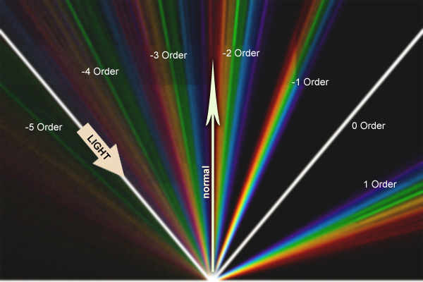
The white ray follows the path traversed by photons for the specular reflection. A viewer watching the material from different angles will see a cyclic rainbow pattern. Each colour corresponds to a different wavelength, while the order indicates its respective integer  . As you can see, the diffraction grating equation is satisfied even for negative values of , since the quantity
  can be negative. From a computational point of view, it makes sense to simplify our search space to only focus on positive values of . The new equation that we will use is:
![\[\left | \sin{\theta_L} - \codt \sin{ \theta_V } \right |= \frac{n \cdot w}{d}\]](https://www.alanzucconi.com/wp-content/ql-cache/quicklatex.com-d1b251f371ffc7aaf5c27629be6837a4_l3.png "Rendered by QuickLaTeX.com")
Conclusion
You can find the complete series here:
- Part 1. The Nature of Light
- Part 2. Improving the Rainbow (Part 1)
- Part 3. Improving the Rainbow (Part 2)
- Part 4. Understanding Diffraction Grating
- Part 5. The Mathematics of Diffraction Grating
- Part 6. CD-ROM Shader: Diffraction Grating (Part 1)
- Part 7. CD-ROM Shader: Diffraction Grating (Part 2)
- Part 8. Iridescence on Mobile
- Part 9. The Mathematics of Thin-Film Interference
- Part 10. Car Paint Shader: Thin-Film Interference
Become a Patron!
You can download the Unity package for the CD-ROM Shader effect on Patreon.
💖 Support this blog
This website exists thanks to the contribution of patrons on Patreon. If you think these posts have either helped or inspired you, please consider supporting this blog.
📧 Stay updated
You will be notified when a new tutorial is released!
📝 Licensing
You are free to use, adapt and build upon this tutorial for your own projects (even commercially) as long as you credit me.
You are not allowed to redistribute the content of this tutorial on other platforms, especially the parts that are only available on Patreon.
If the knowledge you have gained had a significant impact on your project, a mention in the credit would be very appreciated. ❤️🧔🏻
Webmentions
[…] Part 5. The Mathematics of Diffraction Grating […]
[…] Part 5. The Mathematics of Diffraction Grating […]