
Seam carving is a technique that can be used to resize images, which is also known as liquid rescaling. Compared to the traditional resizing tool, it does not “stretch” the image, but it selectively removes the pixels which contain the least amount of information. As a result, it allows to shrink images preserving most of the details.
Seam carving is an example of a context-aware resizing algorithm, as it does not treat images as mere collections of pixels. By all means, it can be considered an AI-powered algorithm. The “AI part” resides in the fact that it is able to identify which pixels to remove on its own. However, it does so without any neural network and—most importantly—without the need to be trained on external data. Hence, it belongs to the field of what I call Classical AI, conversely to the more recent field of Deep Learning. With AI-powered tools becoming more and more popular, I find it helpful to show how a lot can be achieved with some clever algorithms, without the need to train expensive neural network models.
If you are interested in learning more about tools like DALL·E 2 and Midjourney, I would suggest checking one of my most detailed articles titled The Rise of AI Art.
Introduction
The past few months have seen an explosion of AI-based tools and techniques which are able to create and manipulate images at a semantic level. Both DALL·E 2 and Midjourney, in fact, have an actual understanding of both the human language and the content of an image. Many of these techniques have and will keep revolutionising the way in which artists work. Photoshop, for instance, is already relying on generative AI through its new Generative Fill tool; which pretty much integrates the same capabilities exhibited by DALL·E 2 and Midjourney.
But for all the excitement they brought to this industry, generative AI models have also raised serious concerns about copyright, consent, energy consumption and workers’ right. For this reason, it is always good to remind how much can be achieved with some classical AI techniques such as the one presented in this article.
Most people who are working with computers had to, at some point, crop or resize an image. Such a task is not just tedious: is often very challenging. Naively changing the size of an image requires an interpolation step, which often results in aliasing or blurring. It is fairly obvious that cropping and resizing are often insufficient. A better approach would be the identify the elements that are not necessary and remove them from the image. This reduces the image size, but does not require rescaling pixels, hence avoiding any loss of quality on the parts that are unaffected. The techniques that implement this strategy are grouped under the umbrella term of content-aware image resizing.
One of the first algorithms for content-aware resizing is called seam carving and has been introduced by Shai Avidan and Ariel Shamir in 2007, in a paper called Seam carving for content-aware image resizing. Since then, it has been integrated into several other softwares, such as Photoshop CS4 (Content Aware Scaling) and GIMP (Liquid Rescale).
If we want to understand how seam carving works, it is first helpful to understand why much more naïve approaches are not enough.
Column Carving
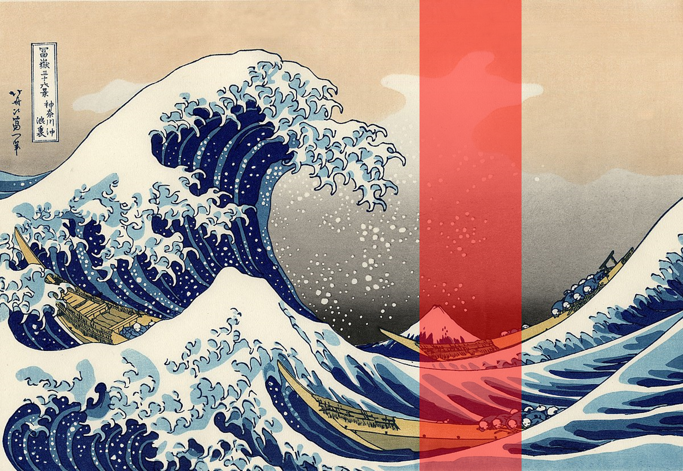
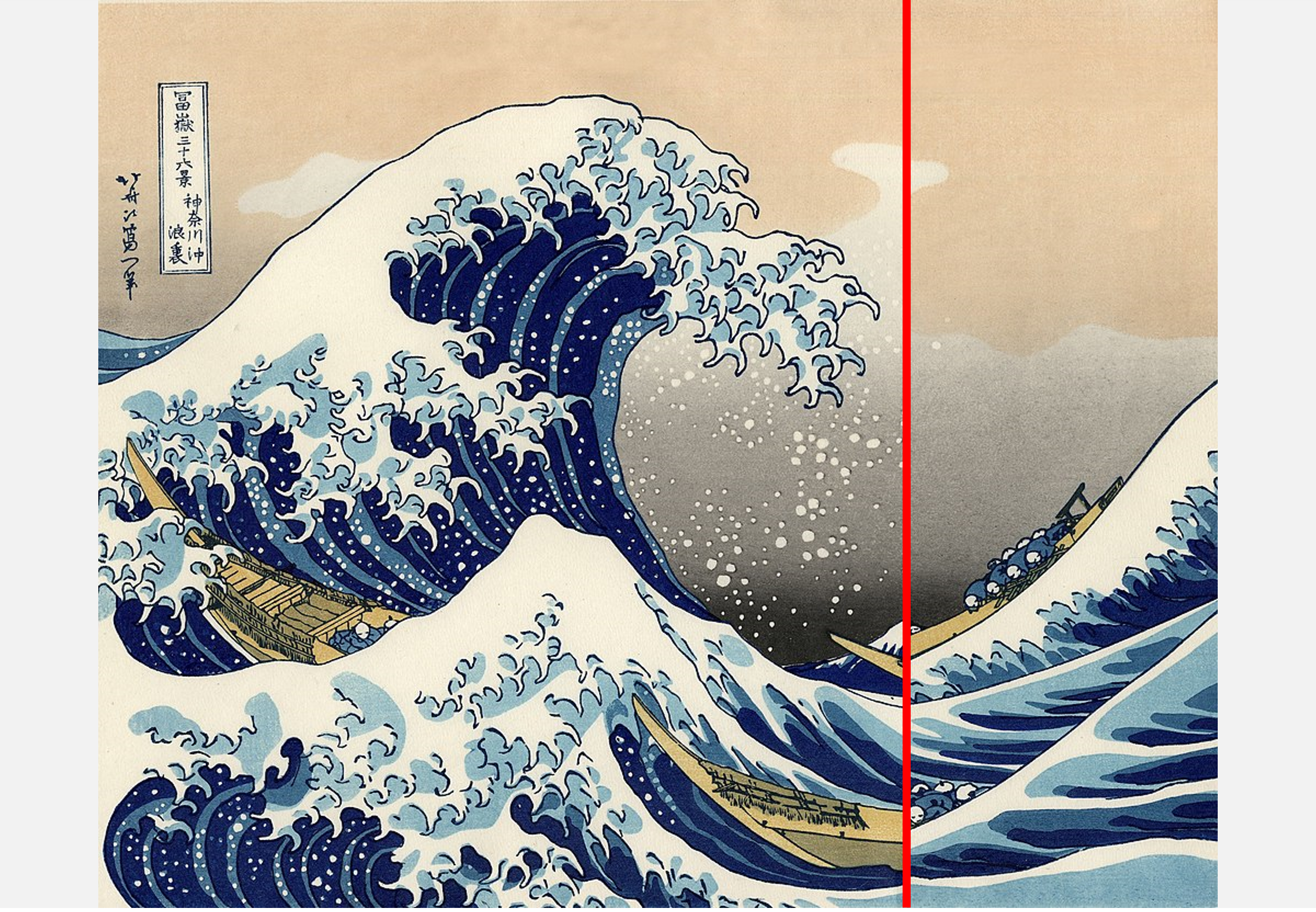
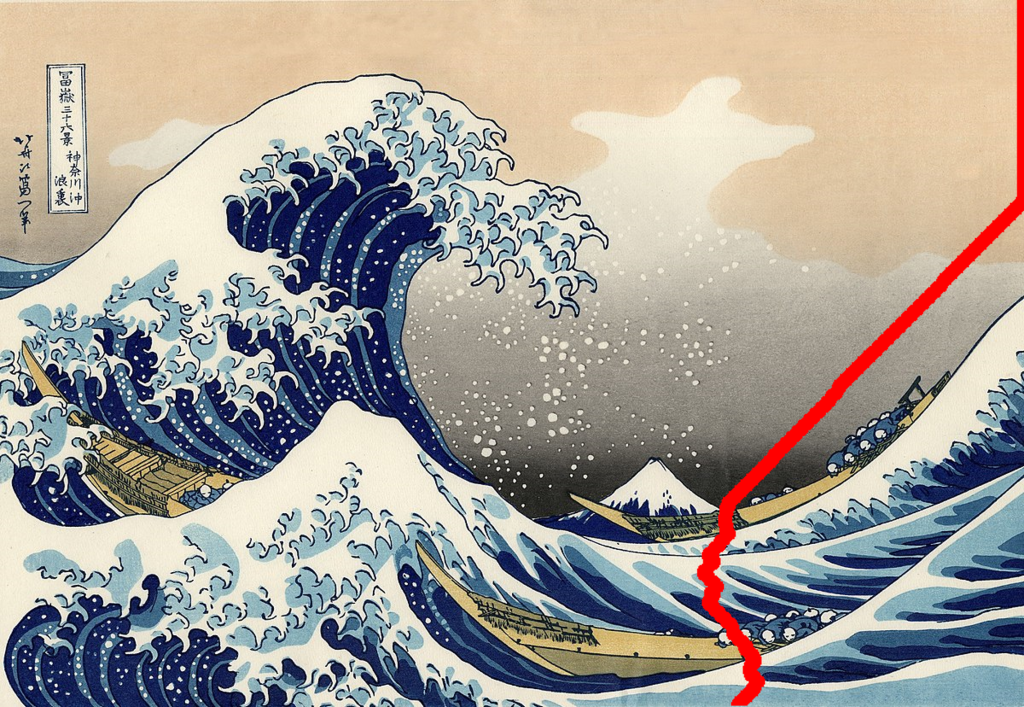
Let’s imagine that we want to reduce the width of a given image by one pixel. For instance, if the original size is 800×600, we might want to downscale it to 799×600. Rescaling all pixels to a new canvas is not ideal, as it would introduce blurring and severe deformations. One possible solution is to remove a column of pixels from the image, and merge the two halves. The procedure, however, is likely to leave a “scar” where the two halves meet. This can be seen in the example below, where a significant vertical slice is cut from “The Great Wave off Kanagawa” by Japanese artist Katsushika Hokusai.
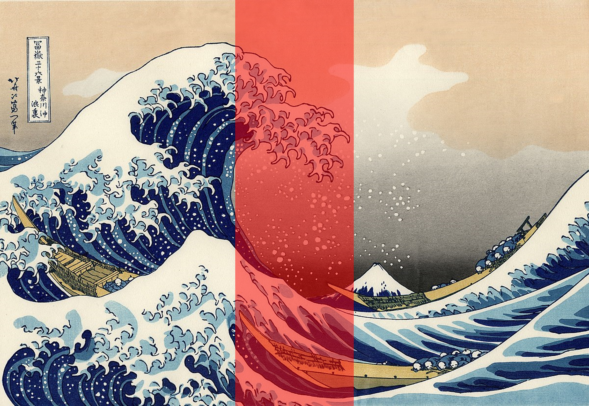

The carving breaks the continuity of the waves, effectively ruining the entire image. The problem is that the edges of the two halves do not really match, creating a large scar. However, it is possible to move the column in such a way that maximises the number of matching colours. Overall, the same number of pixels have been removed, but this time they affect more homogeneous regions of the image, resulting in a more inconspicuous carving.
In the examples above, a significant portion of the image is carved out with a single cut. That is merely a toy example to better visualise how the technique works. But in reality, a much better result can be obtained by removing one column of pixels at a time, and repeating the process until the desired with is reached. This works fairly well because most of the time one-pixel seams are basically invisible.
Pixel Carving
Removing a vertical column of pixels ignores the content of the image. A more promising approach is to identify different areas that minimise the number of colour changes. As can be seen in the image below, this performs much better when it comes to the horizontal seams, but can break the vertical ones.


The reason why this happens is that those blocks are discontiguous, introducing new horizontal seams.
Seam Carving
The idea behind the seam carving algorithm is an evolution of the two techniques seen in the previous sections. The idea is to find a continuous vertical line that minimises the colour difference. These two properties (the continuity and the colour minimisation) ensure the least amount of horizontal and vertical seams, respectively.

The image on the left shows the actual optimal seams calculated by the algorithm that optimally carves one pixel out of each row. The result on the right shows the process, repeated several times.
How it Works…
There are many different ways in which seam carving can be implemented. Regardless of which technique is used, there are three necessary steps:
- Calculating the pixel energy: seam carving attempts to find the seam that minimises the overall impact on the resulting image. In order to do that, we need to quantify how “important” each pixel is within the image (sometimes referred to as energy, weight or density). There is no unique way to do that, and many different metrics can be used. In this tutorial, we have used an edge-detection algorithm known as the Sobel filter. When edges are used as a measure of a pixel’s energy, the resulting seams minimise edge discontinuities.
- Identifying the seam of least energy: vertical seams are connected paths that start from the top of the image and reach the very bottom, allowing to visit each row only once. The energy of a seam is the energy of the pixels it passes through. Seam carving finds the seam with the least amount of energy, corresponding to the seam which has the least impact on the image. There are many possible ways to find such seam, from pathfinding algorithms to dynamic programming.
- Removing the seam: the final step is to remove the seam of least energy, by removing all pixels of its pixels from the image.
Implementation
In order to implement this in Unity, we first need to decide how to encode and manipulate images. The most common way to access them in C# is via the Texture2D class. In order for this to work, however, we need to ensure that the images are configured properly by enabling the “Read/Write Enabled” option is checked in its “Import Settings“. This is important as want to manipulate the image pixels, not just show it on screen.
The energy of the image will be calculated using a Sobel filter, which is a standard edge detection algorithm used in the field of computer vision. While this can be implemented in a C# script, it is best performed via a shader. For this reason, we will also need to write some simple shader code to perform this operation on the input texture. The resulting texture will contain the energy of the image.
There are many ways possible to find the seam of least energy. Given this is effectively a question of finding the shortest path in energy space, a pathfinding algorithm such as Dijkastra’s algorithm would work well. For this tutorial, however, we will use dynamic programming which is how seam carving is more often implemented. This step could potentially be done in a shader, but since it requires many iterations it is best performed in a traditional C# script.
The idea behind dynamic programming is to store intermediate results while we iterate on the image. We can use this to calculate the paths of least energy by iterating on each row. We will refer to this as the energy gradient, which will be properly explained in the following sections.
CalculateEnergy(texture, gradient);
CalculateEnergyGradient(gradient, energy);
FindSeam(energy, seam);
RemoveSeam(texture, seam);
Image Energy
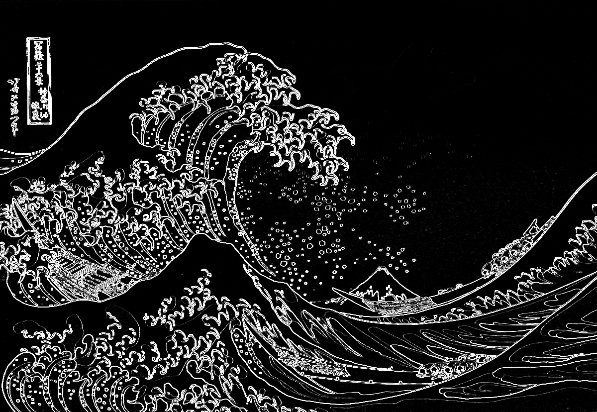
Sobel Edge Detection
There are many different algorithms to detect the edges in an image. A previous article on this blog, Edge Detection in Unity, explained step-by-step how to implement a Laplacian Edge Detector. The one we will use in this article uses a slightly different technique, known as Sobel Edge Detection.
This technique works by calculating, for each pixel, a weighted average of its neighbours’ colours. Instead of working on the R, G and B channels independently, it is not uncommon for these algorithms to collapse them into a single number, presenting the pixel brightness. One of the most common measures used is the perceived luminance, which weights the three colour components by taking into account how the human eye perceives colours, and its sensitivity to different wavelengths (source: W3C):

Most edge detection algorithms actually work like this, but what changes is how such weighted averages are calculated. In the case of the Sobel algorithm, the surrounding 8 pixels are sampled, and processed accordingly to the following matrices (also known as kernels):


The left and right kernels are sensitive to horizontal and vertical lines, respectively. The two kernels above, in fact, strongly react to features that present horizontal or vertical changes in colour. The resulting two weighted averages (often referred to as  and
and  ) are combined using Pythagoras’s theorem to compute the final effect:

The results can be seen below:

Sobel and Laplace are some of the most popular techniques to detect edges, but are not the only ones. Comparing Edge Detection Methods is an interesting read if you want to find out about other techniques, such as the Prewitt and Canny edge detection.
Shader Code
With the theory out of the way, it is not difficult to implement a Sobel edge detection in a Unity shader.
sampler2D _MainTex;
float4 _MainTex_TexelSize; // float4(1 / width, 1 / height, width, height)

#define LUMINOSITY(c) (c.r*.3 + c.g*.59 + c.b*.11)

fixed4 frag (v2f i) : SV_Target
{
	// Samples the nearby pixels
	fixed4 NN = tex2D(_MainTex, i.uv + fixed2(+_MainTex_TexelSize.x, 0) ); // UP
	fixed4 NE = tex2D(_MainTex, i.uv + fixed2(+_MainTex_TexelSize.x, +_MainTex_TexelSize.y) ); // UP RIGHT
	fixed4 EE = tex2D(_MainTex, i.uv + fixed2(0, +_MainTex_TexelSize.y) ); // RIGHT
	fixed4 SE = tex2D(_MainTex, i.uv + fixed2(-_MainTex_TexelSize.x, +_MainTex_TexelSize.y) ); // DOWN RIGHT
	fixed4 SS = tex2D(_MainTex, i.uv + fixed2(0, -_MainTex_TexelSize.y) ); // DOWN
	fixed4 SW = tex2D(_MainTex, i.uv + fixed2(-_MainTex_TexelSize.x, -_MainTex_TexelSize.y) ); // DOWN LEFT
	fixed4 WW = tex2D(_MainTex, i.uv + fixed2(0, -_MainTex_TexelSize.y) ); // LEFT
	fixed4 NW = tex2D(_MainTex, i.uv + fixed2(+_MainTex_TexelSize.x, -_MainTex_TexelSize.y) ); // UP LEFT

	// Luminosity
	fixed NN_lum = LUMINOSITY(NN);
	fixed NE_lum = LUMINOSITY(NE);
	fixed EE_lum = LUMINOSITY(EE);
	fixed SE_lum = LUMINOSITY(SE);
	fixed SS_lum = LUMINOSITY(SS);
	fixed SW_lum = LUMINOSITY(SW);
	fixed WW_lum = LUMINOSITY(WW);
	fixed NW_lum = LUMINOSITY(NW);

	// Gradient
	fixed Gx = NW_lum + 2 * WW_lum + SW_lum - NE_lum - 2 * WW_lum - SE_lum;
	fixed Gy = NW_lum + 2 * NN_lum + NE_lum - SW_lum - 2 * SS_lum - SE_lum;

	// Gradient magnitude
	fixed magnitude = sqrt(Gx*Gx + Gy*Gy);
	magnitude = pow(magnitude, _Power);

	return fixed4(magnitude, magnitude, magnitude, 1);
}
Because this topic has been covered extensively in Edge Detection in Unity, the final code is presented below. You can refer to that article in case you need a more detailed explanation of how it works. But in case it helps, _MainTex_TexelSize.xy is how Unity shaders give access to the size of a texture pixel (a texel) on screen.
C# Code
Once we have a shader that can perform edge detection, we need to apply it to an image. Images in Unity are usually referenced via code as Texture2D. Unfortunately, shaders can only be applied to a different type of texture, known as RenderTexture. Our C# code will need to convert the target image from a Texture2D into a RenderTexure, apply the shader, and then convert it back into a Texture2D. This last step is necessary since individual pixels can only be read from Texture2Ds.
/* Calculates the image energy using the Sobel filter.
 * The calculation is done in a shader.
 * To use the shader on a Texture2D, we first need to
 * convert it into a RenderTexture.
 *
 * Pixels with energy close to ones should be kept.
 * Pixels with energy close to zero can be removed.
 */
void CalculateEnergy(Texture2D texture, Texture2D energy)
{
    // Texture2D -> RenderTexture
    RenderTexture renderTexture = RenderTexture.GetTemporary(texture.width, texture.height, 0, RenderTextureFormat.ARGB32);
    Graphics.Blit(texture, renderTexture, SobelMaterial);

    // RenderTexture -> Texture2D
    RenderTexture previous = RenderTexture.active;
    RenderTexture.active = renderTexture;
        energy.ReadPixels(new Rect(0, 0, renderTexture.width, renderTexture.height), 0, 0);
        energy.Apply();
    RenderTexture.active = previous;
    RenderTexture.ReleaseTemporary(renderTexture);
}
Here we have used RenderTexture.GetTemporary to allocate a temporary render texture. Unity keeps an internal list of such textures, so allocating and releasing new ones does not necessarily cause any new memory allocation. The official documentation suggests it might be more efficient than keeping one allocated at all times.
The way in which we convert a render texture into a 2D texture is also a bit convoluted, as it requires setting the source RenderTexture as the “active” one. The active render texture is a global property shared by all scripts, so to avoid issues it is best to save its previous value and restore it once done.
The code also stores the result image energy in a pre-allocated Texture2D referred to as energy within the function scope. A new texture could have been allocated and returned, but if you want to call this function several times in a row, reusing an existing one will be more efficient.
Energy Gradient
Now that the energy has been calculated using a Sobel filter, we can calculate the seam of least energy using dynamic programming. The algorithm is based on the idea that seams are connected paths that are forced to move in one direction. A vertical seam goes from top to bottom, touching each row only once. This means that, from one row to the next one, a seam can only move by one pixel at a time at most. Thanks to this, finding the path of least energy does not require the adoption of a traditional pathfinding algorithm, but can be performed with a greedy approach.
❓ How can dynamic programming find the shortest path?
If you are familiar with how pathfinding algorithms such as Dijkstra work, you know that they are iterative processes which have to constantly change and update what they believe is the optimal path so far. Dynamic programming, instead, does not seem to do the same, as it never goes back to changing or updating values that were previously calculated. How can then possibly find the shortest path?
The dynamic approach here presented is what Computer Scientists would call a greedy algorithm. However, pathfinding is a complex problem that cannot be solved by greedy algorithms. This is true in the general case, but is not necessarily true when it comes to relaxed versions of the problem.
What we have here is indeed a relaxed version of pathfinding. The reason is that the path can never go back, as the seams are only allowed to pass through each row once. Thanks to this property, we can use a simpler, greedy approach.
We can store such energy gradient in a 2D array. The energy gradient of the first row is the energy of the original pixels. The energy gradient of the pixels from the i-th row is the actual energy of the pixels, plus the minimum of the energies from the three neighbouring pixels from the row above.

What this process does is progressively calculating the cost of the path of least energy starting from each pixel in the top row. Once the energy gradient is calculated, the last row contains the cost of all paths. The image below shows the energy gradient, calculate from top to bottom, showing the preferential seam paths as downward triangles.

The energy gradients can be used to reconstruct the preferential direction of the seams. But let’s just spend a few seconds to appreciate the ghoulish images they can sometimes generate…


The function below, CalculateEnergyGradient, calculates the energy for the top row of the image, and propagates it downward for all the other rows.
void CalculateEnergyGradient(Texture2D energy, float [,] gradient)
{
    Pixels pixels = energy.GetPixelsBlock();

    // Initalisation
    // Top row: uses the energy of the image
    for (int x = 0; x < energy.width; x++)
        gradient[x, energy.height - 1] = pixels[x, energy.height - 1].r;

    // Propagation
    // From top to bottom
    for (int y = energy.height - 1 -1; y >= 0; y--)
    {
        for (int x = 0; x < energy.width; x++)
        {
            // Calculates the minimum gradient
            float minGradient = Mathf.Min
            (
                energy.Get(x - 1, y + 1),
                energy.Get(x    , y + 1),
                energy.Get(x + 1, y + 1)
            );

            gradient[x, y] = pixels[x, y].r + minGradient;
        }

    }
}
The function above relies on two extensions methods specifically designed to make the code less messy: Texture2D.GetPixelsBlock and float[,].Get. They allow sampling pixels outside of the normal range of an image without the need to add explicit boundary conditions. The Pixels class also allow addressing pixels using rows and column, rather than an index like you normally would using Unity’s flattened internal representation (which is a Color[]). These are not strictly necessary, but I think help to make the code clearer. In case you are interested, all of these extra files are present in the Unity package that is available for download through Patreon at the end of the article.
Seam of Least Energy
Once the energy gradient has been calculated, it is possible to reconstruct the seam of least energy by traversing it in reverse. We start from the bottom row, selecting the pixel associated with the minimum energy gradient. That represents the total cost of the path of least energy. Once that has been found, we can simply find neighbouring pixels that have the lowest energy gradient from the row above.
There are many ways to store information about the seam. The one chosen in this article is to use an integer array called seam which indicates, for each row, the column that will be carved out. In the function below, gradient is used as an input and seam as an output.
void FindSeam(float[,] gradient, int [] seam)
{
    // Finds the minimum cost from the bottom row
    float minEnergy = float.PositiveInfinity;
    int minX;
    for (int x = 0; y < gradient.GetLength(0); x++)
        if (gradient[x,0] < minEnergy)
        {
            minEnergy = gradient[x, 0];
            minX = x;
        }

    // First row
    seam[0] = minX;

    // All the other rows
    for (int y = 1; y < gradient.GetLength(1); y++)
    {
        // (x) is the column used from the previous row
        // We have to find the new (x) for the current column
        // This could be (x), (x+1) or (x-1), depending on the energy gradient.

        // Seam index
        int x1 = seam[y - 1];
        int x0 = x1 - 1; // Left
        int x2 = x1 + 1; // Right

        // Seam energy
        float e1 = gradient[x1, y];
        float e0 = x0 >= 0 ? gradient[x0, y] : float.PositiveInfinity;
        float e2 = x2 <= width - 1 ? gradient[x2, y] : float.PositiveInfinity;

        // Calculate the new x
        seam[y] = e0 < e1 ? (e0 < e2 ? x0 : x2) : (e1 < e2 ? x1 : x2);
    }
}
Conclusion
Seam carving is far from being the perfect technique, as there are no guarantees that a seam will not cut through an edge. Generally speaking, seam carving works very well on natural landscapes, where are vast regions of uniform colours (sky, water, grass, land, …). However, it performs poorly on images with complex structures, such as faces. For instance, it does really badly on text, as it tends to ignore the fact that spaces between letters is actually needed.
But when used correctly, it can be the perfect tool to crop and rescale your images.
Additional Resources
- “Seam carving for content-aware image resizing“, the original paper by Shai Avidan and Ariel Shamir
- “Seam Carving Algorithm” by Kirill Lykov
- “What Is Seam Carving? An Explanation And Tutorial” by VICE
- “Seam Carving for Content-Aware Image Scaling” by Math ∩ Programming
- “Seam-Carving and Content-driven Retargeting of Images (and Video)” by Michael Rubinstein (MIT)
Download Unity Package 📦
Become a Patron!The Unity package contains everything needed to replicate the visual seen in this tutorial, including the shader code, the C# scripts and a test scene with the terrain.

Leave a Reply