
This is the second part of a tutorial that will teach you how to build a portable heating device with Arduino. In this post, we will explore how to control a heating resistor with Arduino. This allows to keep your setup at the desired temperature.
- Introduction
- Step 1. Choosing the Sensor
- Step 2. Powering the Heater
- Step 3. Calculating the Base Resistance
- Step 4. Connecting the Components
- Step 5. The Code
- Conclusion
Introduction
In the first part of this tutorial, How to Build a Heater with Arduino – Part 1, we’ve discussed how to create and calibrate the component that will generate the heat. The problem so far is that there is no control over the temperature. If you’ve done your calculation correctly and respected the wattage of your resistors, there is no risk of overheating. However, there’s nothing that prevents your resistors from getting hotter than what you initially intended. This is particularly true if there is no ventilation, or if the heater is in direct contact with a surface that does not dissipate heat very well. The correct (and safe) approach to solve this problem is to introduce a sensor to measure the temperature. If it’s too cold, we’re turning the heating on; if it’s too hot, we’re turning it off. Please, keep in mind that what seems a trivial problem is in actuality incredibly challenging. Designing a responsive device that control an actuator (the heater) based on the reading of a sensor (the temperature) can be a major engineering challenge. This tutorial will provide a very simple solution, and point out how the design can be improved with a little bit of extra Maths.
Choosing the Sensor
Is important to understand that when it comes to temperature, there are a large number of choices. It’s important to understand that different sensors are based on different technologies, hence come with differed limitations and advantages. The main two classes of temperature sensors that are mostly used are integrated circuits and thermistors. Distinguishing them is very easy: the former have three pins, the latter only two.
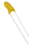 Like the name suggests, thermistors are components which resistance value is very sensitive to temperature changes. Then a voltage difference is applied to its ends, its resistance will vary in response to changes in temperature. Thermistors are somehow a pain to use, since they require additional resistors and a deeper understanding of electronics. The relationship between resistance and temperature is in fact calculated using the Steinhart-Hart equation, which can be scary at first.
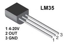 For the above-mentioned reasons, this tutorial will focus on the more Arduino-friendly integrated circuit sensors. For this tutorial, I have used the very common LM35. Two pins are reserved for the reference voltage (ground and 5V); the voltage on the other one will vary between these two, depending on the temperature.
If you want to expand your knowledge on sensors, Arduino sensor temperature comparison has ready-to-use recipes for the most used sensor types.
Powering the Heater
As seen in the previous part of this tutorial, the heater we have designed is likely to require much more current than the one that Arduino can provide. For this reason, it has to be powered separately. A safe and reliable option is to use a traditional phone charger. They usually range from 5V to 9V, and have a limit on the amount of current they can provide. This makes them perfect for this application, as they operate in the a safe range. If you need a serious heating device, you can power you heater directly from the main, although this is going to be very dangerous.
 The problem we have now is to control the flow of current to the heater, using Arduino. This is the perfect time to use a transistor. Transistors are, de-facto, switches. They allow or prevent the flow of current in one direction, based on a specific input. We can use Arduino to turn the switch on and off based on the reading from the sensor. The one I am using for this project is a TIP120, which can operate high voltages. Make sure you have one that can be controller by the voltage provided by an Arduino.
Calculating the Base Resistance
The previous part of this tutorial referred to a battery-operated heater. The new schematics will assume that power comes from a phone charger instead. This changes the input voltage from  to
to  . If we want to dissipate
  of power, we need a total resistance of
  , safely distributed on 8 resistors of
  each (all the calculations are explained in the Part 1). Our new setup requires, to operate at full power, a current of
  . Make sure that the charger you’re using can provide this amount of current, since most of them are capped at
  .
.
It’s common practice to wire a resistor to the base of the transistor. This is the prevent an excessive flow of current that might damage both the transistor and the Arduino. Most designs use resistors between  and
and  . If you have the datasheet of your transistor, you can calculate how much resistance you actually need to be safe. The formula is:
![\[R_B = \left(V_{CC}-V_{BE}\right) \frac{DC_{gain}}{I_C}\]](https://www.alanzucconi.com/wp-content/ql-cache/quicklatex.com-f0876009fb5b3989db9d130703001cdd_l3.png "Rendered by QuickLaTeX.com")
Where:
 : the base resistance to connect to the transistor base;
 : the voltage provided to the base (for Arduino: );
 : the voltage of the transistor when fully on (see below);
 : the load current the transistor has to withstand (as calculated previosuly:
  );
); : the gain of the transistor, when subjected to a current of amps (see below).
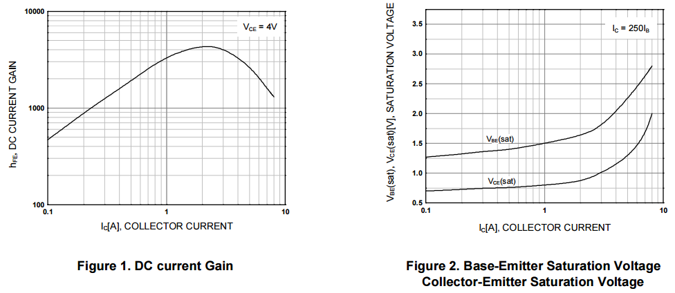
To calculate the we need to refer to the datasheet of the transistor in use. We can read from this graph (TIP120 datahseet) that the TIP120 has a of 3000 at a current of . Similarly, it has a  around
  :
:
By plugging all the numbers, we can calculate that  , meaning we can use a
  resistor.
Connecting the Components
The following diagram shows how all the components have been wired up. The transistor used, TIP120, is a NPN; it means that its emitter pin must be grounded.
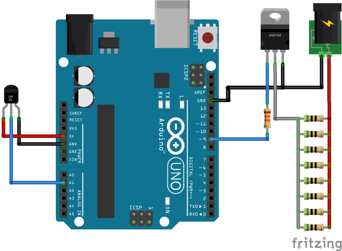
Remember that in order for this design to work, you have to keep the temperature sensor close to the heating elements.
The Code
The final part is to write the logic that operates our heater. During every iteration, Arduino samples the temperature from the sensor and switches the transistor accordingly.
#define PIN_SENSOR A1
#define PIN_SWITCH 9

float target = 30;

void setup()
{
  pinMode(PIN_SENSOR, INPUT);
  pinMode(PIN_SWITCH, OUTPUT);

  Serial.begin(9600);
}

float getTemperature() {
  float data = analogRead(PIN_SENSOR);
  return (5.0 * data * 100.0) / 1024.0; // Celsius
}

void loop()
{
  // Temperature read
  float c = getTemperature();
  Serial.print("Temperature: ");
  Serial.println(c);

  // Regulation
  if (c > target)
  {
    digitalWrite(PIN_SWITCH, LOW);
    Serial.print("\tHeater OFF");
  } else {
    digitalWrite(PIN_SWITCH, HIGH);
    Serial.print("\tHeater ON");
  }

  delay(5000);
}
The equation to read the temperature from the LM35 comes from the official documentation on Arduino Playground (LM35 Higher Resolution).
Conclusion
The code provided in this tutorial is simple, possibly too simple for this application. The sensor used is unreliable, making the system excessively sensitive to temperature small oscillations and noise. A better approach would be to take repeated samples over a longer period of time. Averaging them reduces the effect of noise on the final measure. If you want an optimal solution, however, you can use a Kalman filter. It’s a powerful tool that allows to attenuate and to remove noise from sensors. To read more about it, check the tutorial A Gentle Introduction to Kalman Filters.
Secondly, even the way the heater is controller can be improved. There are several techniques to control an actuator based on a sensor reading. A common approach is to use a PID controller. This will be the topic of a future tutorial.
Other Resources
- Arduino temperature sensor comparison
- How to measure temperature with LM35 and Thermistor 10K using Arduino
- High-Power Control
💖 Support this blog
This website exists thanks to the contribution of patrons on Patreon. If you think these posts have either helped or inspired you, please consider supporting this blog.
📧 Stay updated
You will be notified when a new tutorial is released!
📝 Licensing
You are free to use, adapt and build upon this tutorial for your own projects (even commercially) as long as you credit me.
You are not allowed to redistribute the content of this tutorial on other platforms, especially the parts that are only available on Patreon.
If the knowledge you have gained had a significant impact on your project, a mention in the credit would be very appreciated. ❤️🧔🏻
do you know how I will make a heater with four element and four sensor ?
Hi. Is very hard to give an answer without knowing what you are trying to build and which components are available at your disposal!
I want to design a pocket heater using flexible elements and an Arduino board, which has four elements and four temperature sensors, and how can I connect and use the Bluetooth phone with the desired temperature and control it. . Use PowerBank as a power source for this heater and control the four thermal elements completely independently. The user interface of the heater will be on the mobile phone. MOSFETs are used to turn on and off the elements, and therefore there is no need for relay embedding.
I have no information about the theory of things.
But I have almost all the components.
hi.. recently I had a similar assignment to yours, can I know if you are succeeding design your pocket heater? can I ask you some questions about it, please? thankyou
hi how i used 3 sensor LM35 for control 3 fan 12v?
Hi Daniel.
I believe you can use a very similar approach.
Get the data from your sensor, and then turn the fan on or off based on the temperature.
You can simply replicate this three times, to get the three fans to work. It all depends on which type of fan you have.
You might have to power your fans from an external power supply, like I did for the resistor ladder.
hi, is it possible to use this through a Labview
There is one thing I didn’t understand. Should I plug the 9V battery to Arduino too or would the adaptor be enough? I am just getting started, sorry if that is an easy question.
Hey! I think this is something you should check based on the specification of the board you are using.
Wiring it incorrectly can potentially break it, so I don’t want to take any chances if I don’t know your model.
Usually, you can power Arduino externally either via USB or using a battery pack.
However, some models should not be powered from USB and battery at the same time, as this could damage your USB port.
Thank you very much
Hi, how should I connect the resistor ladder to the phone charger? Thanks .
Is it possible to make this heater with a ds18b20 temperature sensor instead of a tip120?
If I want to spread the resistors out through a garment, can I use connective thread (instead of wire) to build the ladder?
You can, but you have to check the thread specifications to make sure that it can wistand that amount of current!
Also, this is a rather hack-y solution. If you are embedding it in a proper garment, the risk of catching fire might be real! I would personally not wear this device myself, to be honest.
Hello Alan,
Compliment of the season.
Please, I need some help. I am new to arduino world. I want to make a water bath using arduino but I don’t know how to go about this.
A water bath is laboratory equipment made from a container filled with heated water. It is used to incubate samples in water at a constant temperature over a long period of time.
I have UNO, breadboard, couple of resistors, jumper cables, LCD 20×4, switches
Pls, can you be of help in any way?
Hi!
My application was rather rough, in all fairness. I did not need a very fine control over the temperature, which justified my solution given how inexpensive it was.
For a lab application, you might need a much finer and reactive way to control the temperature.
You can probably buy an electric heating pad (such as the ADA1481), or a Metal Ceramic Heater Plate Heating Element. There might be components that are better suited (and safer!) to heat water, but I do not have much experience with them.
Also, if you need very fine control over the temperature, you will need a much more precise way of controlling the temperature. For instance, implementing a Kalman Filter ( https://www.alanzucconi.com/2015/06/28/a-gentle-introduction-to-kalman-filters/ ).
I hope this helps getting started!
I am new to Arduino world .I need your help.I want to make immersion heater with Arduino control so what changes I have to make?
Hi! This solution will not work under water!
Due to safety reasons, you are better off buying a water heater and using Arduino to turn it on/off.
Is possible know e temperature max generate?
Hey man, could I use the TIP as the heater element? If we generate a big enough Ic current (TIP can withstand 5A), then TIP will warm. We can attach to TIP a heat sinker, as well the LM35 sensor by using a thermal paste.
If I want to power 300w dc heater to turn on at degrees can I use this
Thank you! this is exactly what I need to do for a project
Hi, I would like to use your approach to heat small aluminum board as heater of my cup of tea (not boiling, but keep my cup and tea warm). What is the limits of temperature what can be “handled” without any issues.?
Is this TP120 able to heat on 60-70’C without any big issues? (use more of them)
Thank you.