

Many game developers are easily scared by electronics. Even if Arduino has shifted most of the workload on its software side, there are applications which still need a good knowledge of circuitry. This post will teach how to use LEDs, from the most basic model to the most advanced one:
- Part 0. Theory
- Part 1. Basic LED
- Part 2. RGB LED
- Part 3. Neopixel strip
- Conclusion
LEDs are perfect for creative projects, and they can be also be used to create entire games, such as the mesmerising Line Wobbler.
This post belongs to a series of tutorials aiming to teach game developers how to build their own alternative game controllers:
- How to integrate Arduino with Unity
- How to build a distance sensor
- How to hack any IR remote controller
Part 0. Theory
LED is the acronym for Light-Emitting Diode. As the name suggests, it is a component that emits light. The term diode indicates an electric component which allows current to flow only in one direction. Hence, all diodes have a polarity, meaning that they have a positive (anode) and a negative (cathode) side. An LED is generally used in forward bias condition, meaning that its positive side is attached to the positive side of the circuit. In order to work, the LED requires a certain voltage which is referred as forward voltage or  . If less voltage is provided, the LED won’t allow current to flow, hence interrupting the circuit like an open switch. As soon as the right voltage is applied, current starts flowing. The LED will draw all the current it receives, converting it into light. Each LED has a value called forward current, or
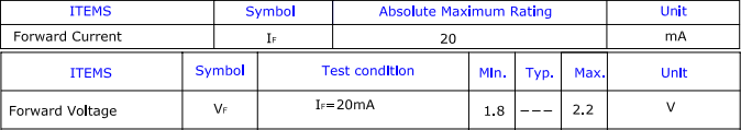
  , which refers to the nominal amount of current it should receive. A standard red, orange or yellow LED are typically rated for 2.0V at 20mA. Before using a new LED you should always check its specifications: both forward voltage and forward current can be found in its datasheet and they typically look like this:
Current limiting resistor
As mentioned in the previous section, LEDs draw all the current they receive. Unless you provide a way to limit this amount, it’s very likely any LED will burn when connected to a battery. This is why LEDs are commonly coupled with resistors, which allows to regulate the amount of current received. Is important to pick a resistor which will ensure that only an amount of current equal to  is going through the LED. Ohm’s Law relates current, voltage and resistance as
  , and it can be used to find the right resistors. We know the voltage remaining in the circuit after the activation of the LED, which is
  . We also know the current that we need. , which has to be expressed in Amperes rather than milliAmperes:
  . Now, the only remaining thing is to apply Ohm’s Law. If we assume the LED is going to be powered by an Arduino,
  , hence:
![\[R=\frac{V_{battery} - V_F}{\frac{I_F}{1000}}=\frac{3V}{0.02A}=150\Omega\]](https://www.alanzucconi.com/wp-content/ql-cache/quicklatex.com-2fe3efc257ee6bb6681b8c5bf326370a_l3.png "Rendered by QuickLaTeX.com")
You can refer to the following table to know which resistor you should use:
| Color | |
|
Resistor | Color | |
|
Resistor | ||
| Red |  |
 |
 |
Green |  |
|
 |
||
| Orange | |
|
|
Blue | |
|
|
||
| Yellow | |
|
|
White | |
|
|
||
| UV | |
 |
 |
IR |  |
|
 |
For more complicates circuits, you can also refer to this LED calculator.
Part 1. Basic LED
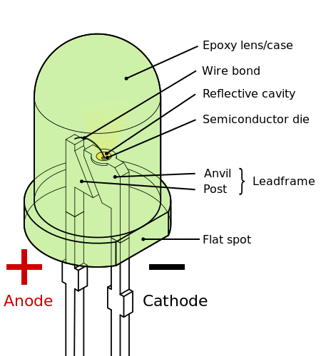
Basic LEDs usually come in a transparent epoxy case, which also works as a lens. The positive side, called anode, is recognisable because is connected to a longer pin. Alternatively, the cathode side of the LED is always flat.
Once you have identified the positive and negative sides, you can attach it to an Arduino Uno, providing that you have the right resistor.

By connecting your LED to the 5V output, it will always be on. If you want to be able to turn it on and off, you should attach it to a pin and use digitalWrite to write HIGH or LOW to it. The following code is taken from the Blink sketch from Arduino:
void setup() {
	pinMode(3, OUTPUT);
}

void loop() {
	digitalWrite(3, HIGH);
	delay(1000);
	digitalWrite(3, LOW);
	delay(1000);
}
Colour is not the only thing you should look for when buying LEDs. The brightness, for instance, is a very important parameter. Typical LEDs are rated 20mA, while very bright ones tend to be rated at 50mA or 100mA.
Pulse Width Modulation
As a general rule, is safe to provide less current than the one indicated in . This often causes the LED to shine less, but is hard to control. If you want your LEDs to fade reliably, there is another technique called pulse width modulation. Arduino has a function called analogWrite, which is used to output square waves made alternating LOW and HIGH voltages. The period of a square wave in Arduino, also called duty cycle, is approximately 2ms, meaning that Arduino has a frequency of 500Hz. The parameter provided to analogWrite determines how much time of the duty cycle is spent outputting a HIGH value.

When analogWrite is used on an LED, it turns it on and off very fast. The human eye cannot refresh fast enough to see the LED blinking at 500Hz, so the duty cycle is perceived as a difference in brightness. Arduino comes with a sketch called Fade which uses PWM to fade an LED in and out:
int led = 9;
int brightness = 0;
int fadeAmount = 5;

void setup() {
  pinMode(led, OUTPUT);
}

void loop() {
  analogWrite(led, brightness);

  brightness = brightness + fadeAmount;
  if (brightness == 0 || brightness == 255)
    fadeAmount = -fadeAmount ;

  delay(30);
}
PWM is the standard way used to change the brightness of LEDs in Arduino, but is only available on certain pins. The ones which can be used for PWM have a tilde next to them.
Part 2. RGB LED
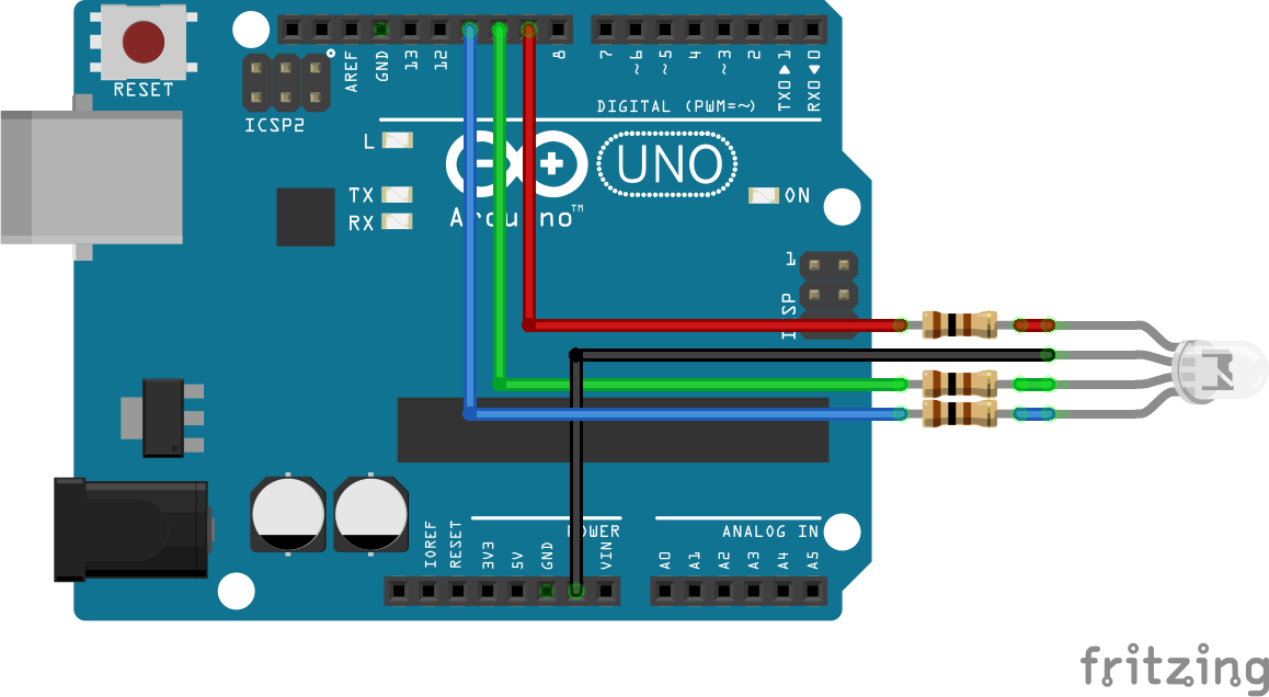
The actual components that emits light inside an LED is tiny. So tiny that there are components which can fit three of them in the same space. The most commonly used is the RGB LED, which has four pins. One is a shared ground, while the other three drive the R, G, and B components. They are, de-fact, three independent LEDs and requires three different PWM pins to be controlled. Each one requires its own resistor.
int pin_r = 9;
int pin_g = 10;
int pin_b = 11;

void changeColour (int r, int g, int b) {
	analogWrite(pin_r, r);
	analogWrite(pin_g, g);
	analogWrite(pin_b, b);
}
Part 3. Neopixel strip
The problem with RGB LEDs is that each one of them requires three PMW pins. Arduino Uno as only six, meaning that only two RGB LEDs can actually be used at the same time. If you want to connected dozens or hundreds of RGB LEDs, another approach is needed. Adafruit has created NeoPixel strip, which requires only three pins to drive several individual RGB LEDs. Using NeoPixels is a little bit more complicated.
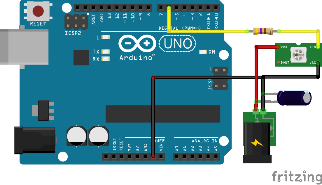
- Power supply. Each pixel in a NeoPixel strip draws 60mA when is shining at full brightness; Arduino can only provide 500mA thought its 5V pin. If you are using more than 8 pixels, you need an external 5V power supply. Since NeoPixels are very sensitive to voltage fluctuation, you should put a capacitor between the positive and negative sides of the power supply. Capacitors takes time to charge, and offer protection from spikes. Adafruit suggests to use a 1000 µF, 6.3V capacitor. On some models, the 5V and ground pins are called VDD and VSS, respectively.
- Data input. Neopixels require a 470Ω resistor on its data line, marked as DIN. It is very important that the grounds of the Arduino and the power supply are aligned. To do this, you should connect both grounds together.
- The library. In order to use the NeoPixel strip, you need to download and install its library. If you are not familiar with the procedure, you should follow the installation steps here.
- Initialisation. Once the library is installed, the NeoPixel strip can be used. The following code initialises a strip of 60 pixels, connected through pin 6.
#include <Adafruit_NeoPixel.h> Adafruit_NeoPixel strip = Adafruit_NeoPixel(60, 6); // (pixels, pin) void setup() { strip.begin(); strip.setBrightness(255); // Full brightness strip.show(); // All pixels off } - Code. NeoPixel LEDs can be addressed individually with the function
setPixelColor. To commit the chances, you have to invoke theshowfunction.strip.setPixelColor(n, red, green, blue); strip.show();
NeoPixels are a rather sophisticated piece of technology. On the Adafruit website you can find more information how to use them.
The LEDs used in Adafruit components looks very different from the ones presented in the previous sections. They are often called SMD LEDs, which stands for Surface Mounted Device.
Conclusion
There are so many things you can do with LEDs, especially RGB ones. Adafruit NeoPixels can be rather expensive, but there are so many incredible things you can build of of them.
Other resources
- LED Throwies: How to use LEDs and coin batteries;
- LED basics: A very nice article which explains how to use LEDs;
- Resistors for LEDs: A more detailed guide on how to use resistors for LEDs;
- Wallet-size LED Resistance Calculator: An old fashioned resistance calculator made out of paper.
💖 Support this blog
This website exists thanks to the contribution of patrons on Patreon. If you think these posts have either helped or inspired you, please consider supporting this blog.
📧 Stay updated
You will be notified when a new tutorial is released!
📝 Licensing
You are free to use, adapt and build upon this tutorial for your own projects (even commercially) as long as you credit me.
You are not allowed to redistribute the content of this tutorial on other platforms, especially the parts that are only available on Patreon.
If the knowledge you have gained had a significant impact on your project, a mention in the credit would be very appreciated. ❤️🧔🏻
Webmentions
[…] have recently written a tutorial on how to use LEDs and NeoPixels strips. They are at the heart of many existing alternative games, […]
[…] Everything You Need to Know About LEDs […]