
Part 1, Part 2, Part 3, Part 4, Part 5
We can safely say that Unity3D has made game development easier for a lot of people. Something where it still has a long way to go is, with no doubt, shader coding. Often surrounded by mystery, a shader is a program specifically made to run on a GPU. It is, ultimately, what draws the triangles of your 3D models. Learning how to code shaders is essential if you want to give a special look to your game. Unity3D also uses them for postprocessing, making them essential for 2D games as well. This series of posts will gently introduce you to shader coding, and is oriented to developers with little to no knowledge about shaders.
Introduction
The diagram below loosely represents the three different entities which plays a role in the rendering workflow of Unity3D:
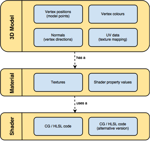
3D models are, essentially, a collection of 3D coordinates called vertices. They are connected together to make triangles. Each vertex can contain few other informations, such as a colour, the direction it points towards (called normal) and some coordinates to map textures onto it (called UV data).
Models cannot be rendered without a material. Materials are wrappers which contain a shader and the values for its properties. Hence, difference materials can share the same shader, feeding it with different data.
Anatomy of a shader
Unity3D supports two different types of shaders: suface shaders and fragment and vertex shaders. There is a third type, the fixed function shaders, but they’re now obsolete and will not be covered in this series of posts. Regardless which type fits your needs, the anatomy of a shader is the same for all of them:
Shader "MyShader"
{
	Properties
	{
		// The properties of your shaders
		// - textures
		// - colours
		// - parameters
		// ...
	}

	SubShader
	{
		// The code of your shaders
		// - surface shader
		//    OR
		// - vertex and fragment shader
		//    OR
		// - fixed function shader
	}
}
You can have multiple SubShader sections, one after the other. They contain the actual instructions for the GPU. Unity3D will try to execute them in order, until it finds one that is compatible with your graphics card. This is useful when coding for different platforms, since you can fit different versions of the same shader in a single file.
The properties
The properties of your shader are somehow equivalent to the public fields in a C# script; they’ll appear in the inspector of your material, giving you the chance to tweak them. Unlike what happens with a script, materials are assets: changes made to the properties of a material while the game is running in the editor are permanent. Even after stopping the game, you’ll find the changes you made persisting in your material.
The following snippet covers the definition of all the basic types of properties you can have in a shader:
Properties
{
	_MyTexture ("My texture", 2D) = "white" {}
	_MyNormalMap ("My normal map", 2D) = "bump" {}	// Grey

	_MyInt ("My integer", Int) = 2
	_MyFloat ("My float", Float) = 1.5
	_MyRange ("My range", Range(0.0, 1.0)) = 0.5

	_MyColor ("My colour", Color) = (1, 0, 0, 1)	// (R, G, B, A)
	_MyVector ("My Vector4", Vector) = (0, 0, 0, 0)	// (x, y, z, w)
}
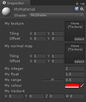 The type 2D, used in lines 3-4, indicates that the parameters are textures. They can be initialised to
 white, black or gray. You can also use bump to indicate that the texture will be used as a normal map. In this case, it is automatically initialised to the colour #808080, which is used to represent no bump at all. Vectors and Colors always have four elements (XYZW and RGBA, respectively).
The image on the left shows how these properties appear in the inspector, once the shader is attached to a material.
Unfortunately, this is not enough to use our properties. The section Properties, in fact is used by Unity3D to give access from the inspector to the hidden variables within a shader. These variables still need to be defined in the actual body of the shader, which is contained in the SubShader section.
SubShader
{
	// Code of the shader
	// ...
	sampler2D _MyTexture;
	sampler2D _MyNormalMap;

	int _MyInt;
	float _MyFloat;
	float _MyRange;

	half4 _MyColor;
	float4 _MyVector;

	// Code of the shader
	// ...
}
The type used for texture is sampler2D. Vectors are float4 and colours are generally half4 which use 32 and 16 bits, respectively. The language used to write shaders, Cg / HLSL, is very pedantic: the name of the parameters must match exactly with the one previously defined. The types, however, don’t need to: you won’t get any error for declaring _MyRange as half, instead of float. Something rather confusing is the fact that if you can define a property of type Vector, which is linked to a float2 variable; the extra two values will be ignored by Unity3D.
⭐ Suggested Unity Assets ⭐
The rendering order
As already mentioned, the SubShader section contains the actual code of the shader, written in Cg / HLSL which closely resembles C. Loosely speaking, the body of a shader is executed for every pixel of your image; performance here is critical. Due to the architecture of the GPUs, there is a limit on the number of instructions you can perform in a shader. It is possible to avoid this dividing the computation in several passes, but this won’t be covered in this tutorial.
The body of a shader, typically looks like this:
SubShader
{
	Tags
	{
		"Queue" = "Geometry"
		"RenderType" = "Opaque"
	}
	CGPROGRAM
	// Cg / HLSL code of the shader
	// ...
	ENDCG
}
Lines 8-11 contain the actual Cg code; the section is signalled by the CGPROGRAM and ENDCG directives.
Line 3, before the actual body, introduces the concept of tags. Tags are a way of telling Unity3D certain properties of the shader we are writing. For instance, the order in which it should be rendered (Queue) and how it should be rendered (RenderType).
When rendering triangles, the GPU usually sort them according to their distance from the camera, so that the further ones are drawn first. This is typically enough to render solid geometries, but it often fails with transparent objects. This is why Unity3D allows to specify the tag Queue which gives control on the rendering order of each material. Queue accepts integer positive numbers (the smaller it is, the sooner is drawn); mnemonic labels can also be used:
Background(1000): used for backgrounds and skyboxes,Geometry(2000): the default label used for most solid objects,Transparent(3000): used for materials with transparent properties, such glass, fire, particles and water;Overlay(4000): used for effects such as lens flares, GUI elements and texts.
Unity3D also allows to specify relative orders, such as Background+2, which indicates a queue value of 1002. Messing up with Queue can generate nasty situations in which an object is always drawn, even when it should be covered by other models.
ZTest
It is important to remember, however, that an object from Transparent doesn’t necessarily always appear above an object from Geometry. The GPU, by default, performs a test called ZTest which stops hidden pixels from being drawn. To work, it uses an extra buffer with the same size of the screen its rendering to. Each pixel contains the depth (distance from the camera) of the object drawn in that pixel. If we are to write a pixel which is further away than the current depth, the pixel is discarded. The ZTest culls the pixels which are hidden by other objects, regardless the order in which they are drawn onto the screen.
Surface versus vertex and fragment
The last part which needs to be covered is the actual code of the shader. Before doing this, we’ll have to decide which type of shader to use. This section will give a glimpse of how shaders look like, but it won’t really explain them. Both surface and vertex and fragment shaders will be extensively covered in the next parts of this tutorial.
The surface shader
Whenever the material you want to simulate needs to be affected by lights in a realistic way, chances are you’ll need a surface shader. Surface shaders hide the calculations of how light is reflected and allows to specify “intuitive” properties such as the albedo, the normals, the reflectivity and so on in a function called surf. These values are then plugged into a lighting model which will output the final RGB values for each pixel. Alternatively, you can also write your own lighting model, but this is only needed for very advanced effects.
The Cg code of a typical surface shader looks like this:
CGPROGRAM
// Uses the Labertian lighting model
#pragma surface surf Lambert

sampler2D _MainTex;	// The input texture

struct Input {
	float2 uv_MainTex;
};

void surf (Input IN, inout SurfaceOutput o) {
	o.Albedo = tex2D (_MainTex, IN.uv_MainTex).rgb;
}
ENDCG
Line 5 inputs a texture, which is then set as the Albedo property of the material in line 12. The shader uses a Lambertian lighting model (line 3), which is a very typical way of modelling how light reflects onto an object. Shaders which only use the albedo property are typically called diffuse.
The vertex and fragment shader
Vertex and fragment shaders work close to the way the GPU renders triangles, and have no built-in concept of how light should behave. The geometry of your model is first passed through a function called vert which can alter its vertices. Then, individual triangles are passed through another function called frag which decides the final RGB colour for every pixel. They are useful for 2D effects, postprocessing and special 3D effects which are too complex to be expressed as surface shaders.
The following vertex and fragment shader simply makes an object uniformly red, with no lighting:
Pass {
CGPROGRAM

#pragma vertex vert
#pragma fragment frag

struct vertInput {
	float4 pos : POSITION;
};

struct vertOutput {
	float4 pos : SV_POSITION;
};

vertOutput vert(vertInput input) {
	vertOutput o;
	o.pos = mul(UNITY_MATRIX_MVP, input.pos);
	return o;
}

half4 frag(vertOutput output) : COLOR {
	return half4(1.0, 0.0, 0.0, 1.0);
}
ENDCG
}

Lines 15-17 converts the vertices from their native 3D space to their final 2D position on the screen. Unity3D introduces the UNITY_MATRIX_MVP to hide the maths behind it. After this, line 22 gives a red colour to every pixel. Just remember that the Cg section of vertex and fragment shaders need to be enclosed in a Pass section. This is not the case for simple surface shaders, which will work with or without it.
Conclusion
This post gently introduces the two types of shaders available in Unity3D and explains when to use one over the other. Four more posts will follow, explaining how to implement them in details. An extra post will introduce screen shaders, which are used for postprocessing 2D images.
- Part 1: A gentle introduction to shaders in Unity3D
- Part 2: Surface shaders in Unity3D
- Part 3: Physically Based Rendering and lighting models in Unity3D
- Part 4: Vertex and fragment shader in Unity3D
- Part 5: Screen shaders and postprocessing effects in Unity3D
💖 Support this blog
This website exists thanks to the contribution of patrons on Patreon. If you think these posts have either helped or inspired you, please consider supporting this blog.
📧 Stay updated
You will be notified when a new tutorial is released!
📝 Licensing
You are free to use, adapt and build upon this tutorial for your own projects (even commercially) as long as you credit me.
You are not allowed to redistribute the content of this tutorial on other platforms, especially the parts that are only available on Patreon.
If the knowledge you have gained had a significant impact on your project, a mention in the credit would be very appreciated. ❤️🧔🏻
The tag doc link should be:
http://docs.unity3d.com/Manual/SL-SubShaderTags.html
Thank you, thank you, thank you !
the part5 link url is wrong should be 2015/07/28 not /6/28
Thank you! 😀 It should be fixed now! 😀
This is a great series of articles on a topic that I feel really needs posts like this. This first part still leaves me wondering the same thing as the official Unity documentation does. About SubShaders you write
“Unity3D will try to execute them in order, until it finds one that is compatible with your graphics card.”
This is pretty much the same the documentation says, but to me it seems that this is only a partial truth. I’ve seen that even though the code within the CGPROGRAM section of a subshader obviously has an effect, what is set as Fallback, still makes a difference. Now, as Fallback (according to the documentation) essentially is the same thing as setting the subshaders from the fallback shader to be next, this means that even though subshader 1 is run, it also runs (at least partially) subshader 2. So, does this mean that the process of finding the the first compatible one is done separately for consequent render queues or something? Or am I understanding something else incorrectly here?
Hello Alan.
Got here after reading your Unity 5 shader cook book.What a fantastic piece of knowledge and resource it is. Thank you so much for putting it out there. I’ll be making it required reading for my students.
Got a mail id ?
I have one request. Can you perhaps do a breakdown / tutorial on how to create a Matte shadow material ( also known as shadow catcher ).
Packt does videos too. Hope you make a video series.
Cheers and all the best.
Behram
Thanks you very much !
>When rendering triangles, the GPU usually sort them according to their distance from the camera, so that the further ones are drawn first. This is typically enough to render solid geometries, but it often fails with transparent objects.
Isn’t that the opposite? Try to render closer opaque geometry first (so you don’t run pixel shaders for things that end up hidden), but for transparent items, render further geometry first so that it alpha blends properly?
Typically you do start from back to front (it’s called the painter’s algorithm). Depth testing takes care of not drawing pixels that are occluded.
Sorry depth testing has nothing to do with your question (the painter’s algorithm does though)
Thank you!!! super simple !!
Informative article
I was searching for this information on google